
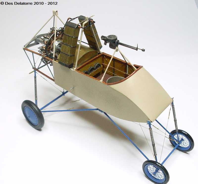
This will be my first ever scratch build of a model so it will be a learning experience for me. I started by obtaining a full set of 1:32 scale plans, these will help tremendously throughout the build. I also purchased Windsock Data File No. 135 plus I have downloaded a lot of photos from the net, so hopefully I will have enough information to complete this model and maybe have it look very much like the real aeroplane.
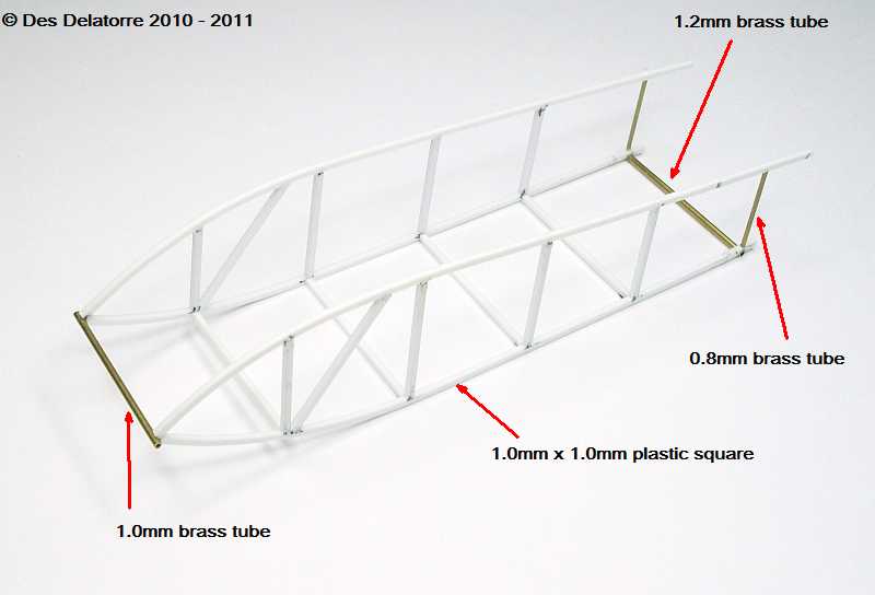
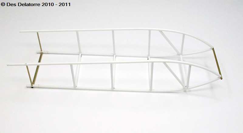
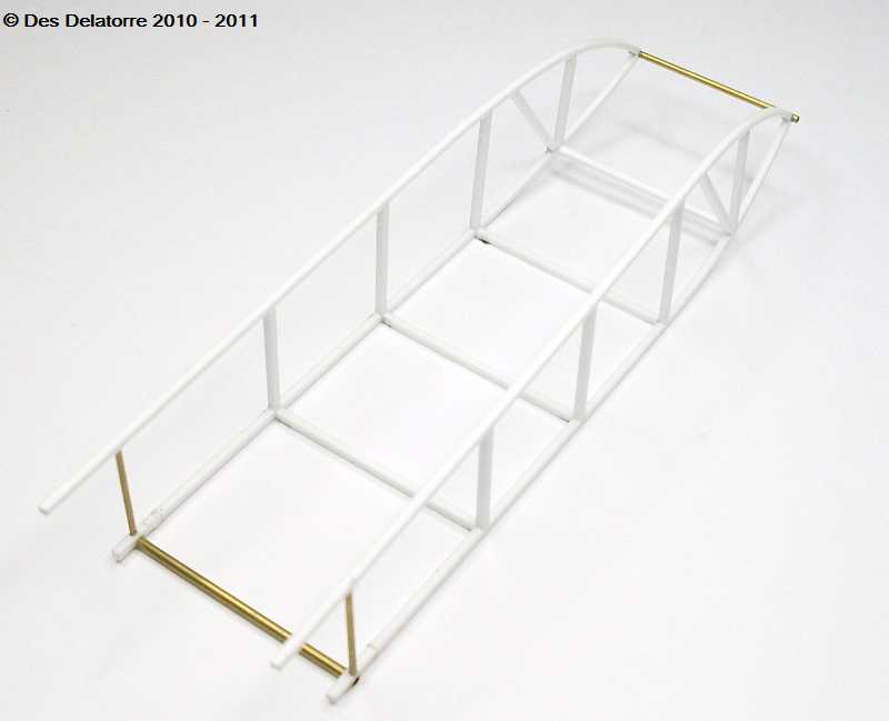
Work has commenced on the fuselage frame work, for this I have used 1.0mm x 1.0mm plastic strips. Each strip was positioned over the plan and cut to the appropriate size, once all parts were cut I taped the top and bottom frame members to the plan then glued the uprights. Once these were set I removed them from the plan then again positioned the sides on the plan and glued the bottom frames. The front tube which will take the forward undercarriage is 1.0mm brass tube, the rear tube has been recessed into the frame and is 1.2mm brass tube, this will support the rear undercarriage and the rear of the bottom wing with 0.9mm solid steel rod which will be inserted into the brass tube and held with CA.. The small rear upright tube is 0.8mm brass tube, this will support the engine plus there will be bracing brass tubes as well.
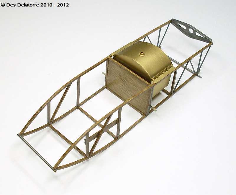
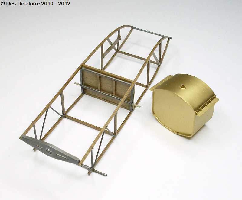
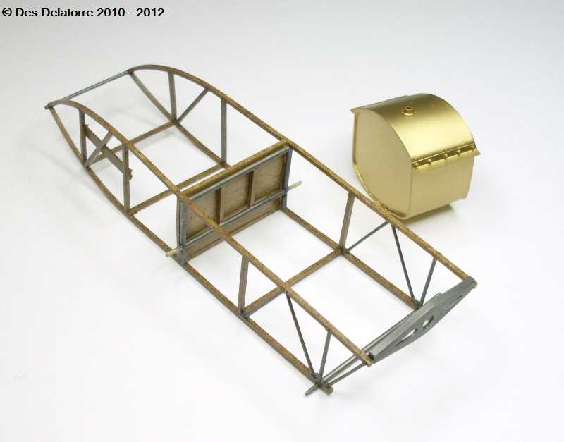
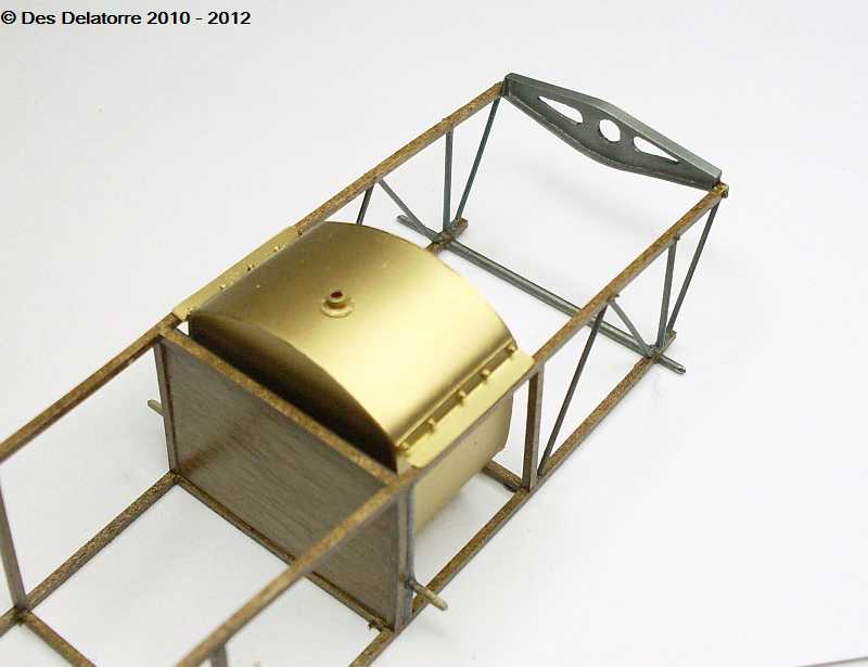
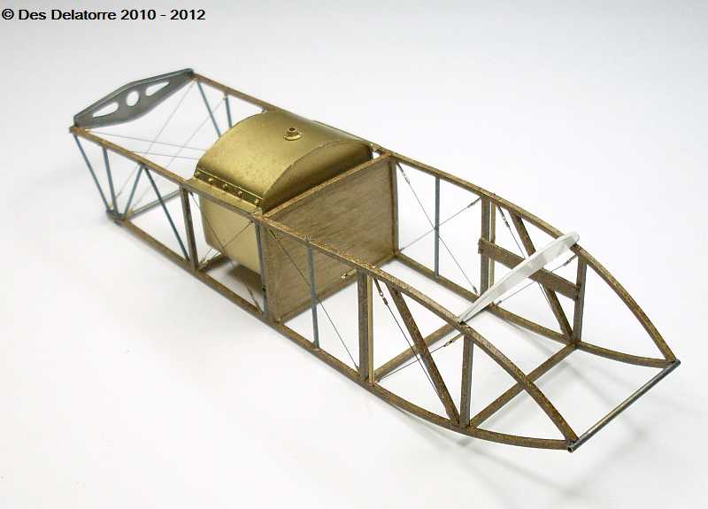
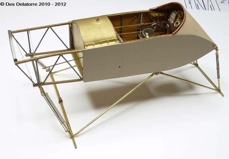
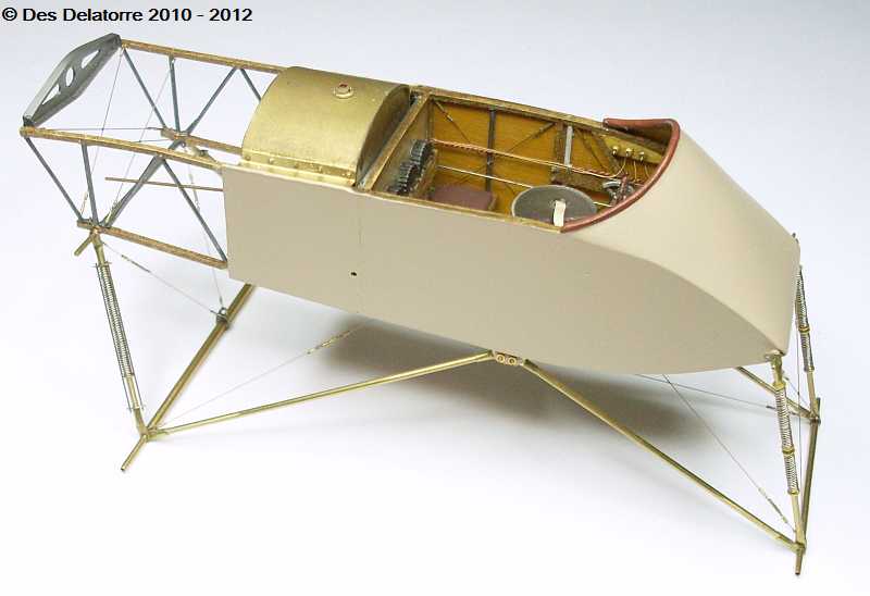
The fuselage frames have been base coated with Gunze yellow then Raw Umber oil paint was used to add the wood colour. The plywood bulkhead was done with the same paint except applied thinner. The rear engine mount is cut from 0.5mm plastic card with the slots filed to shape. The fold was done by using 0.18mm plastic card cut to 2.0mm wide and glued to the edge of the previous cut mount, it is painted with Mr Metal Color Stainless. The fuel tank is made from 0.5mm plastic card and made as per the plan, the mounting plates are bent coke can metal and the mounting bolts are Grandt line nuts, it is all held together with CA. The fuel tank was sprayed with Mr Metal Color Brass. Behind the bulkhead is 1.2mm brass tube, the two upright tubes were flattened where the bottom cross member fits, a 1.2mm hole was drilled here to take the cross piece, again a length of 0.9m steel rod was inserted through the tube, this will become the bottom wing forward mount. The brace tubing at the rear of the fuselage frame work is 0.65mm copper wire which has been flattened on the bottom end, bent to the appropriate angle and a 0.4mm hole drilled through, this hole will take a grandt line bolt set, the upright metal support is 0.8mm brass tube. All metal fixtures have been painted using Mr Metal Color Stainless, when dry they were lightly buffed.
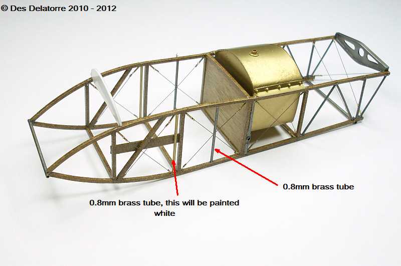
I have done most of the fuselage frame rigging, for this I used 0.12mm monofilament. I drilled 0.3mm holes into the fuselage frame and fitted small turnbuckles, to these I attached the mono and secured it with a small brass sleeve and a small drop of CA. All the rigging lines have been painted with Mr Metal Color Stainless. I have also added some 0.8mm brass tube to the framing in the cockpit area, the rear one has been paint with the stainless paint whilst the forward one will be painted white, this one will support the machine gun frame work support. I have cut the instrument panel from 0.5mm plastic card and sat it in roughly the position it is going to sit. There are two sets of bracing wires which run across the back of the fuselage frame where the engine will mount, these are also 0.12mm mono with turnbuckles.
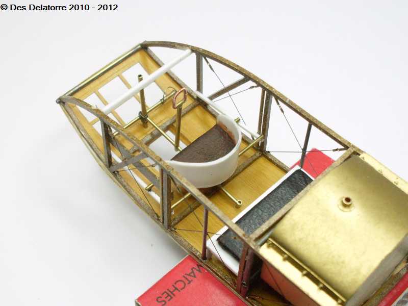
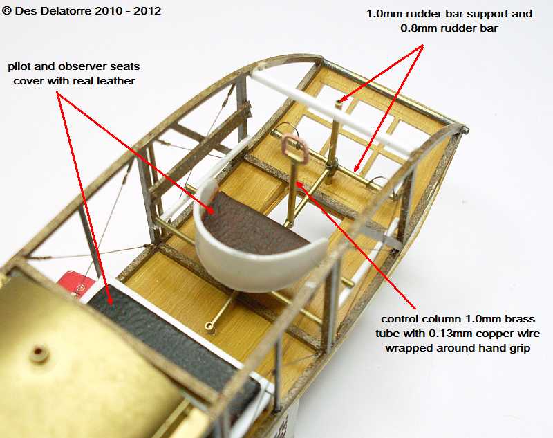
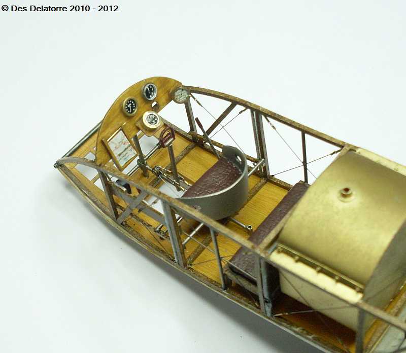
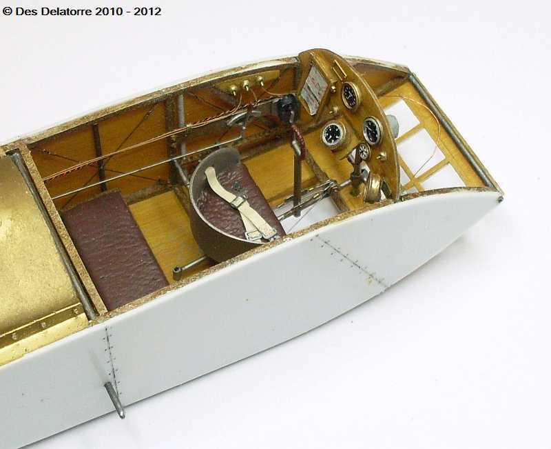
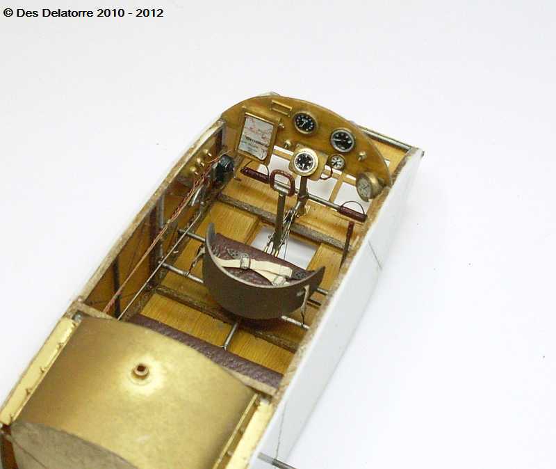
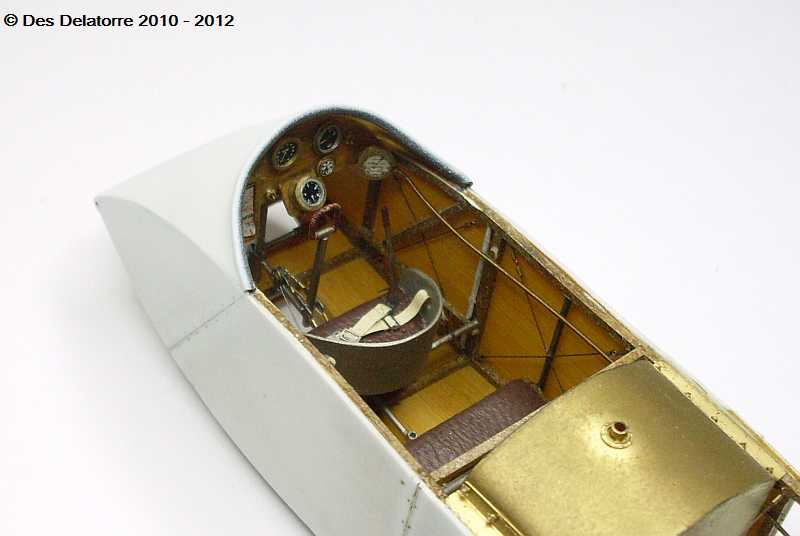
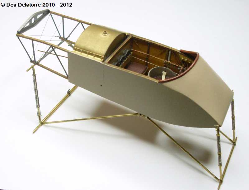
I made the rudder bar from 0.8mm brass tube, a small length of plastic tube was placed over each end to act as the foot support then I used 0.18mm wire for the stirrups. The rudder bar support rod is 1.0mm brass tube. The control column is 1.0mm brass tube with a 0.8mm hole drilled at the bottom to fit over the 0.8mm brass tube support. The hand grip is shaped from 0.35mm copper wire then wrapped in 0.13mm copper wire, I still need to add the pulley forward of the control column plus the control cable connectors to the bottom of the control column. The pilot seat is made from 0.5mm plastic card and the seat cushion is real leather painted with burnt sienna oil paint. The observers bench seat is on a frame made from 1.0mm square stock and the seat cushion is also cover with real leather, it needs to be painted with the burnt sienna oil paint. The floor is now fixed in position. The two rods supporting the pilot seat are 0.8mm brass tube.
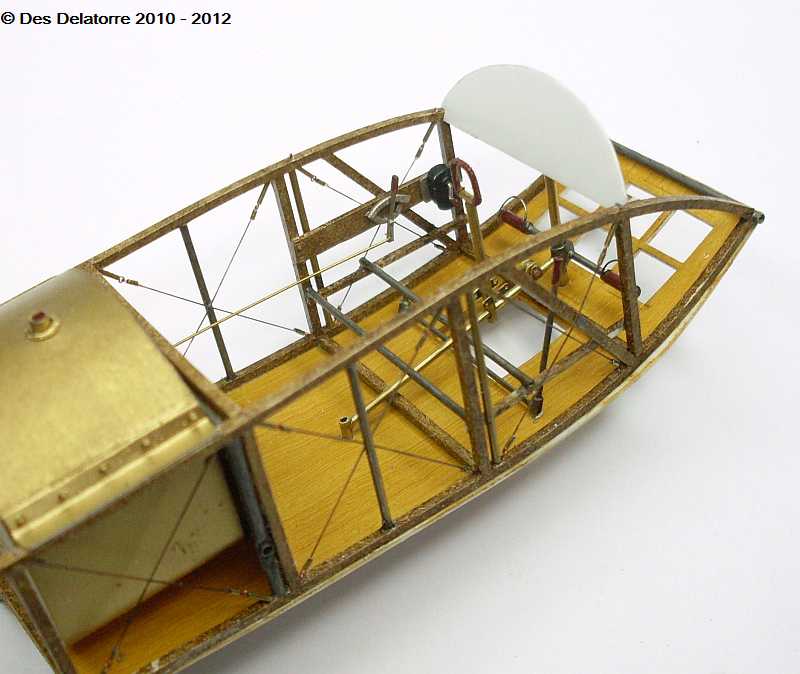
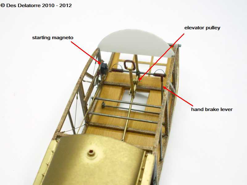
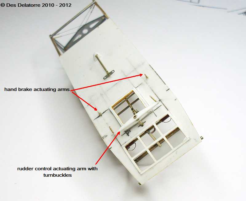
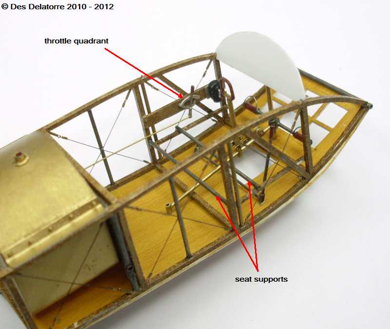
The throttle quadrant is made from 0.4mm brass tube bent to shape then flattened, the gate for the quadrant is 0.65mm copper wire bent to shape then flattened, it is CA’d to the frame. The lever is 0.3mm brass tube flattened at the bottom end and two 0.3mm holes drilled, one for the pivot pin the other for the linkage, a small piece of tiny plastic tube is slipped on the top to act as the hand grip. The throttle actuating rod is a length of 0.3mm brass tube. The starting magneto is made from scrap plastic block, it was cut then sanded to shape, the winding handle is bent from 0.3mm brass tube, a small brass washer is glued to the face of the magneto where the handle mounts. The rudder actuating bar under the fuselage is made from 0.5mm plastic card with a 1.2mm brass tube centre, this mounts onto the 1.0mm brass tube rudder bar support rod. The hand brake lever is fom 0.6mm brass tube with a small plastic tube on the top for the hand grip.
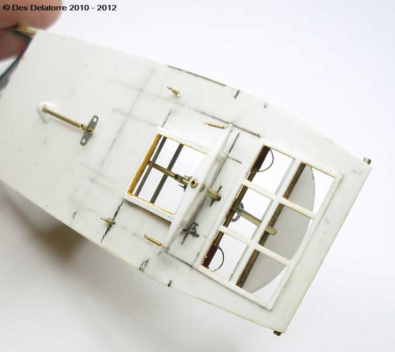
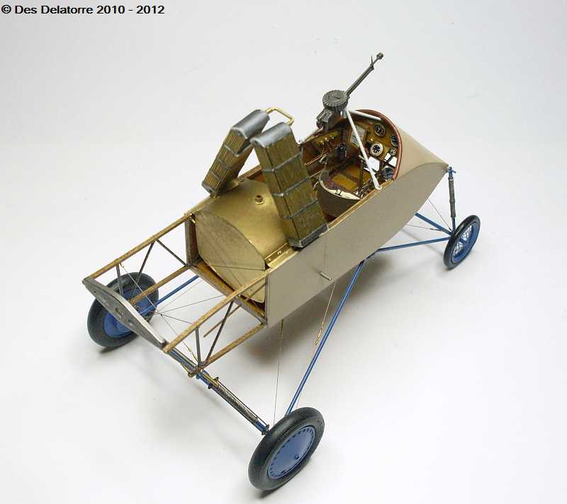
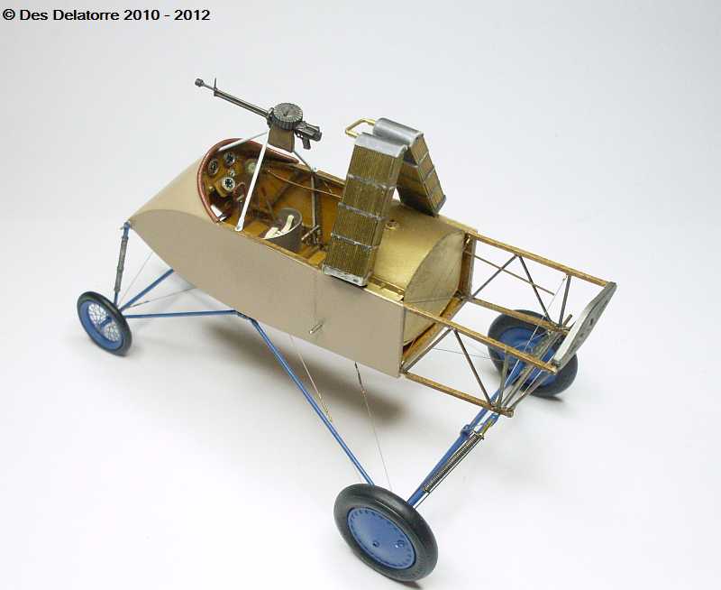
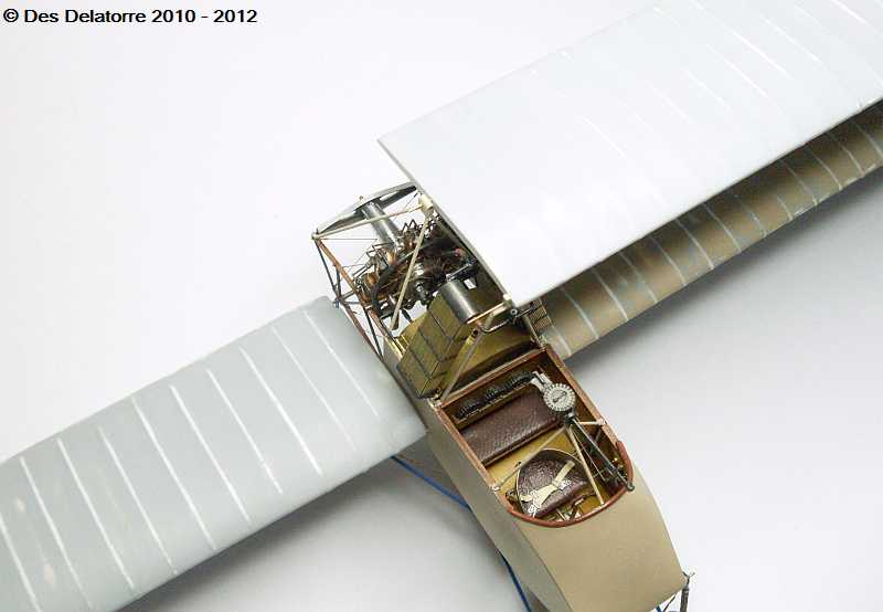
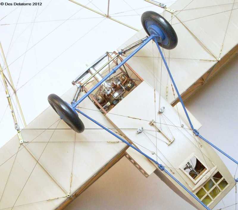
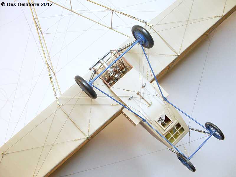
The control column is now fitted but unpainted, it has the elevator pulley mounted at the forward end of the support tube plus control cable connectors mounted to the column. The pictures of the bottom of the plane show the two brake cable attachment linkages protruding through the floor. Because of the large windows on the bottom of the fuselage I will have to detail the back of the instrument panel.
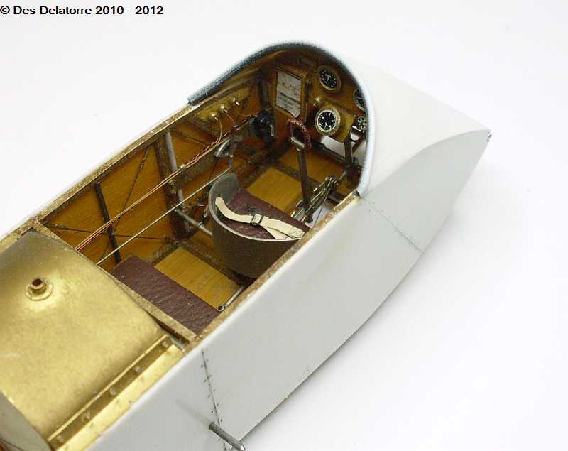
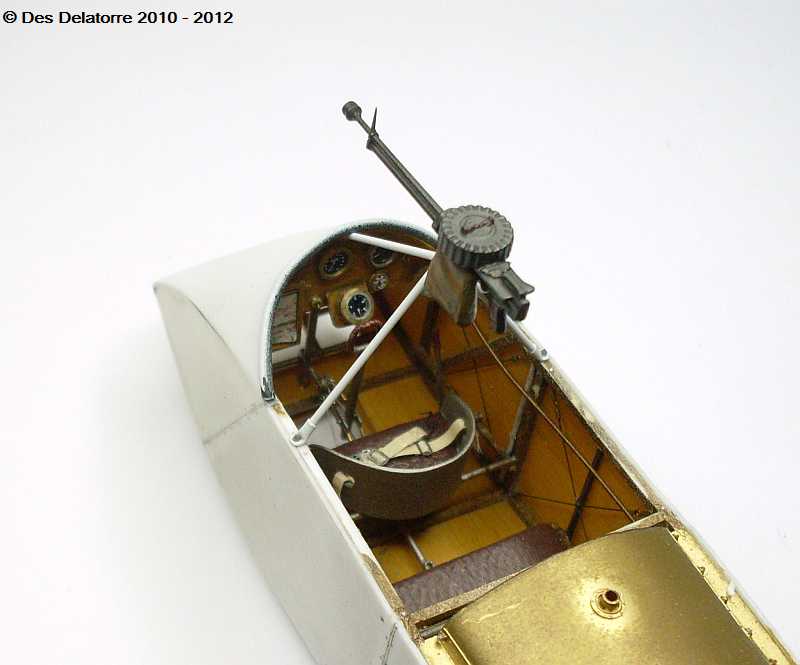
I have started making the instrument panel, for the instruments I am using various sizes of brass and aluminium tubes with airscale instrument decals. I have also rigged the control column with 0.12mm mono and 0.4mm brass sleeves, the forward control wires run over the pulley then return back under the pilot seat. The instrument panel and some of the instruments are not yet fixed in position.
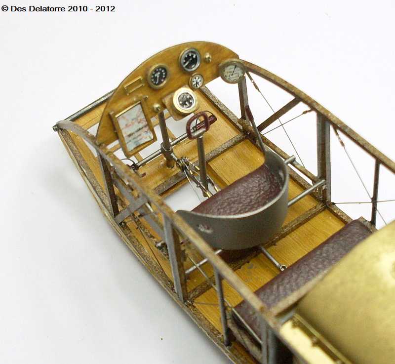
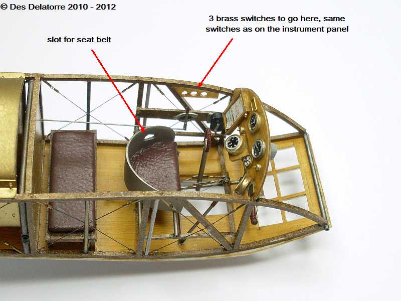
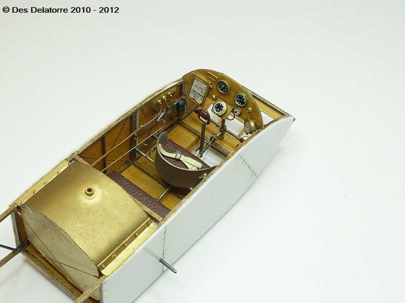
The instrument panel is nearly finished, I still need to add the text to the makers plate and I will also add some wiring. All the instruments are now fixed to the panel as are the two brass switches. There will be another 3 switches fitted to the left side of the cockpit, the switches are made from 1.3mm brass tube with the forward face rounded, the small hole down the centre of the tube is enlarged just slightly with a 0.7mm drill, then a short length of 0.3mm brass tube is glued into the hole to simulate the switch lever, this can be positioned either up or down (on or off)The observers bench seat id now fixed, I will be fitting seat belts to the pilot seat next.
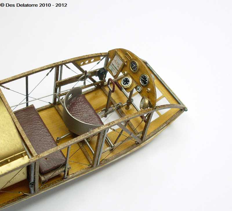
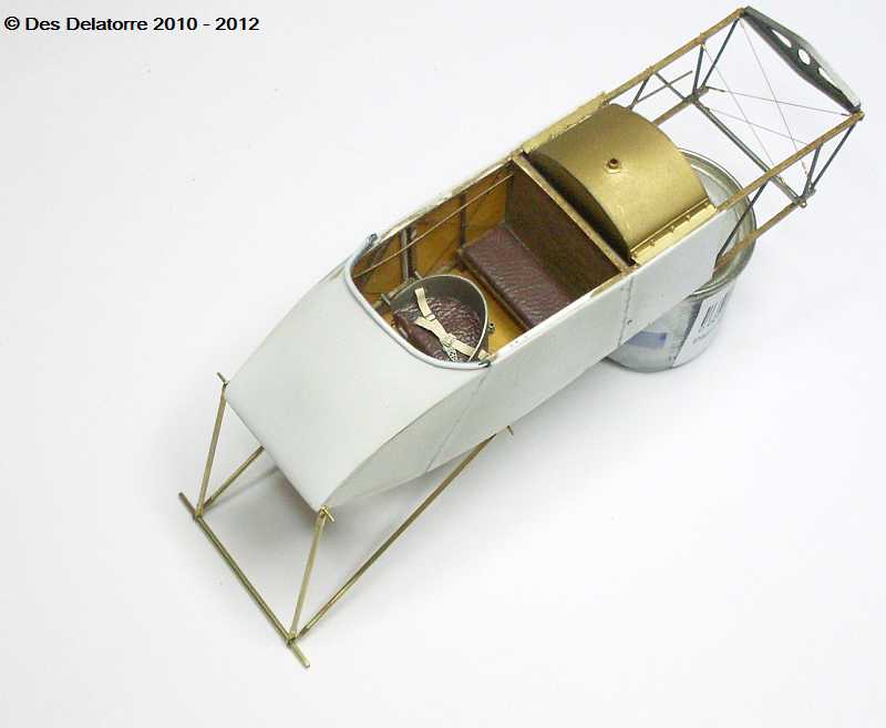
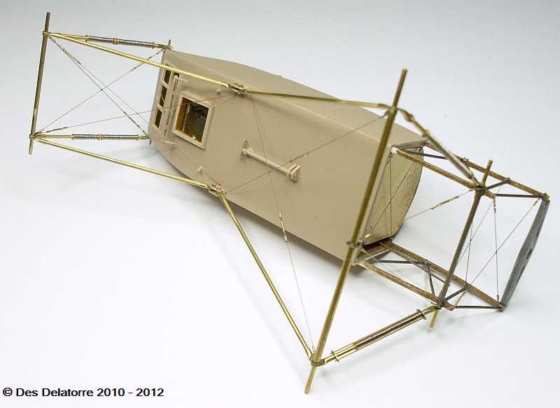
As can be seen in the photos, I have added the sides to the fuselage, for this I used 0.5mm plastic card. I also scored the panel lines and added the ‘nail’ heads. I used one of HGW seat belt sets for the pilot seat, these fitted nicely through the slots on the sides of the seat and anchored to the seat support.
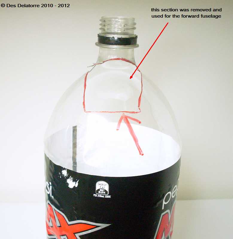
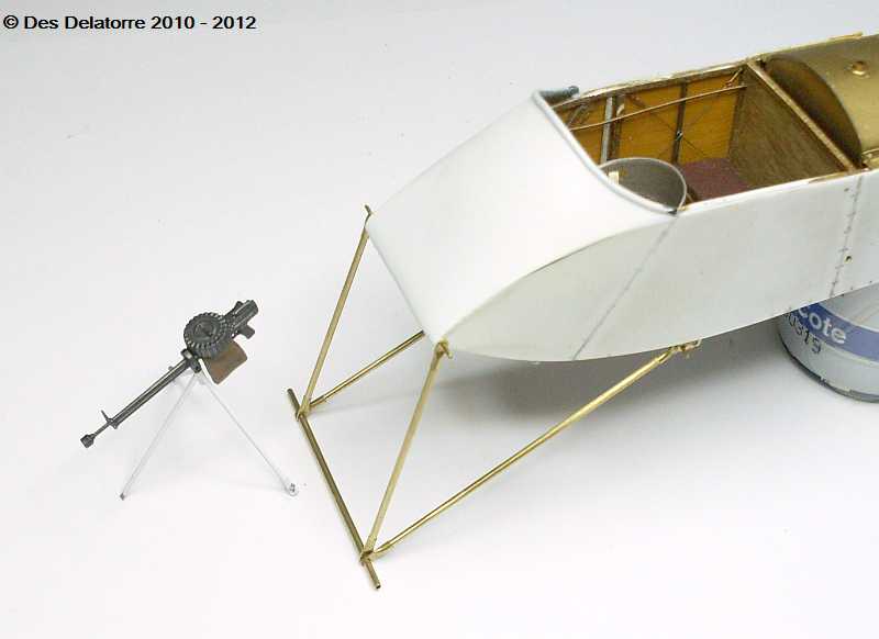
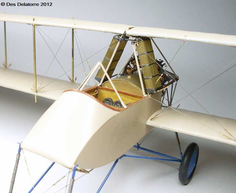
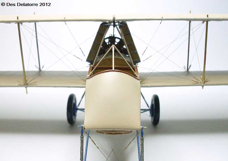
To make the front fuselage covering required having a piece with a compound curve, that is curved in two directions. I discovered that the section marked in the photo of a 2L Pepsi bottle was very close to the shape that I needed. It was a simple matter of making a paper template first over the nose of the model then transferring that shape to the appropriate area on the bottle, I cut it out roughly with a scalpel then trimmed it to size with a sharp pair of scissors.

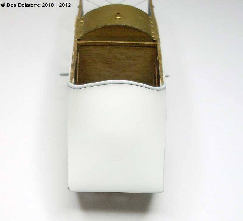
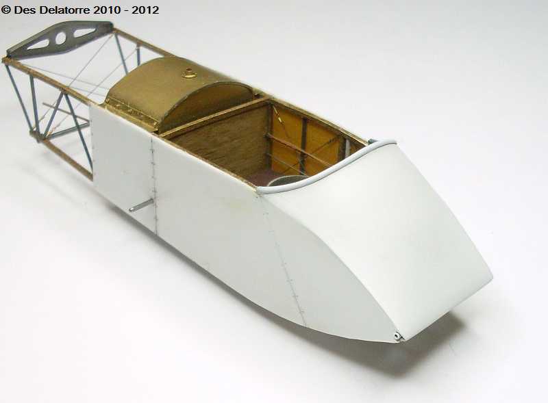
The result is a nicely fitting forward fuselage covering which is pretty close to the correct shape, this is a very easy way to make a curved section without the use of vac forming equipment. The Pepsi bottle plastic is very close to 0.3mm in thickness so it is an ideal size for this purpose. Once the glue had set I sanded the edges and the nose then applied a coat of white paint so as to pick up any faults. The beading around the top edge is done with a very small diameter electrical wiring, I stripped the outer insulating plastic off then split this down the centre over the entire length, this was then fitted over the fuselage covering above the instrument panel, small drops of CA holds it in place.
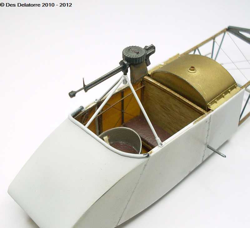
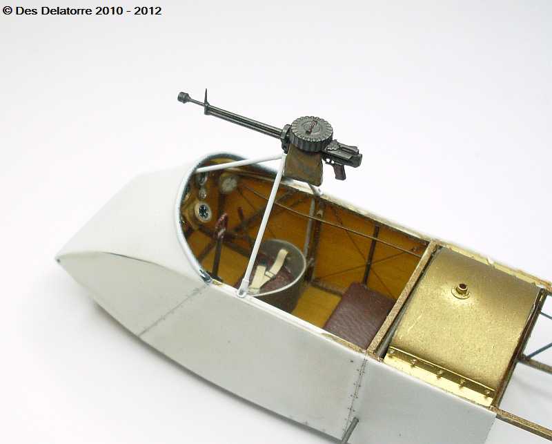
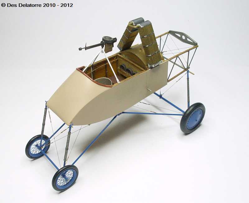
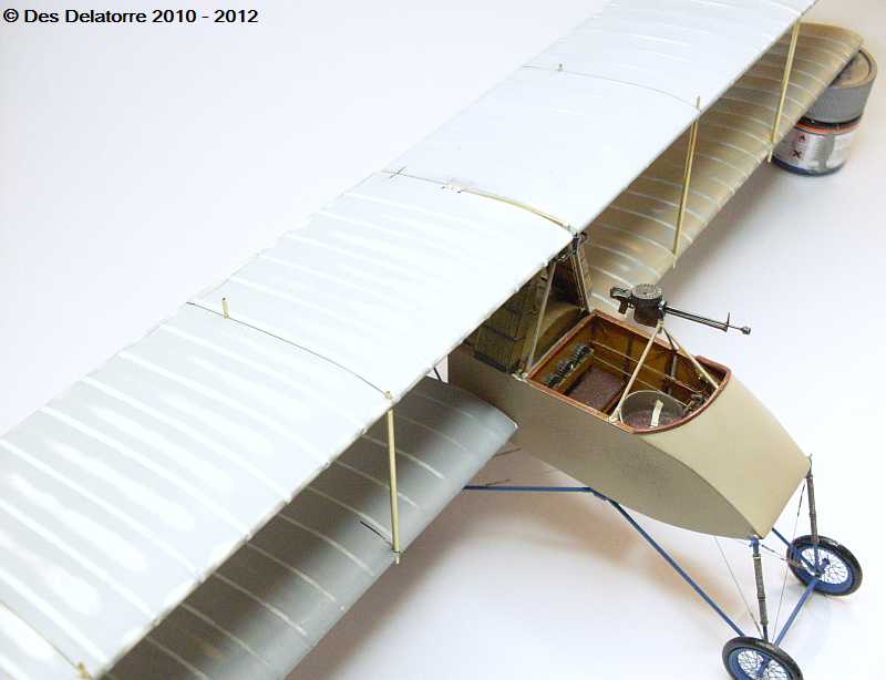
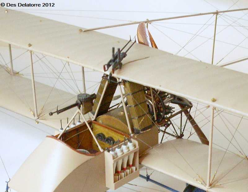
There were quite a few variations to the machine gun mounting frame, this appears to be the most common one used. I made the frame from 0.7mm brass tube, these tubes fitted inside a 1.0mm brass tube flattened on one end, a 0.4mm hole drilled through the flat section then the tube cut to a short length, this acts as the mount onto the frame, a Grandt line nut/bolt holds the mount to the fuselage frame. The machine gun mount is a short length of 1.2mm brass tube, I drilled a 0.4mm hole through the tube and a length of 0.3mm brass tube was inserted through the hole, this tube then fitted inside the 0.7mm tube and when CA was applied it forms a very strong assembly. I also filed a bevel on the top of the tubes where they meet the machine gun mount. The forward part of the frame sits on top of the instrument panel, this mounts to the machine gun mount the same way as the other two tubes, another 0.4mm hole was drill and again a small pin was inserted into the tube to give me a very positive and strong assembly. The machine gun is a left over from my spares box, I modified it slightly to make it look more like what was used, I also added a spend cartridge collection bag on the side of the gun, this was used to stop the spent shells flying back and going through the propeller. The gun is painted with Mr Metal Dark Iron and lightly buffed, the bag is painted with Gunze Dark Earth while the gun frame is painted with Gunze Flat White. The whole machine gun frame with gun is only sitting for photo purposes, it will be removed while I do the undercarriage.
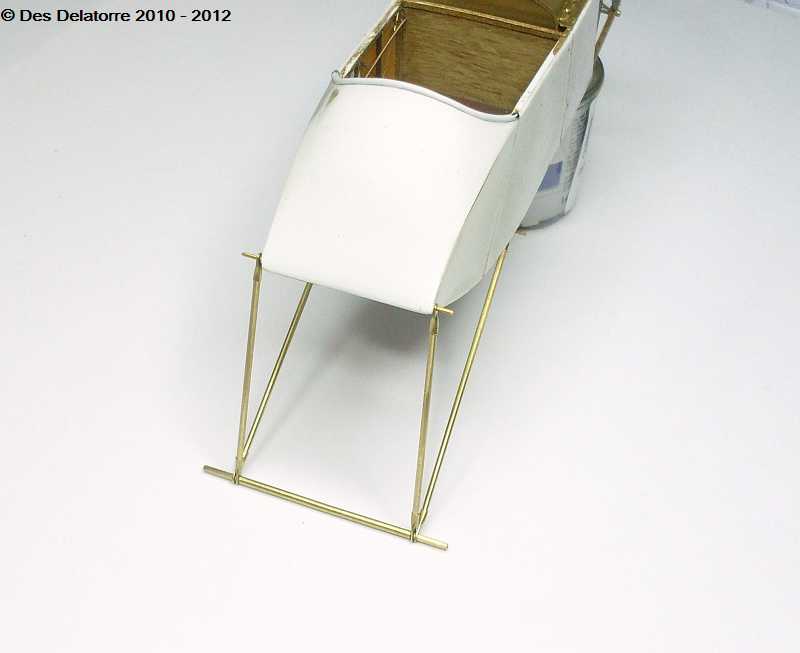
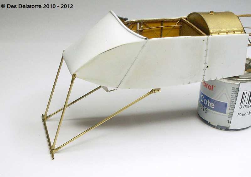
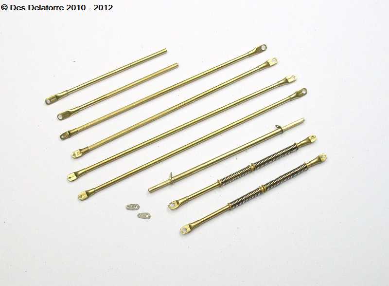
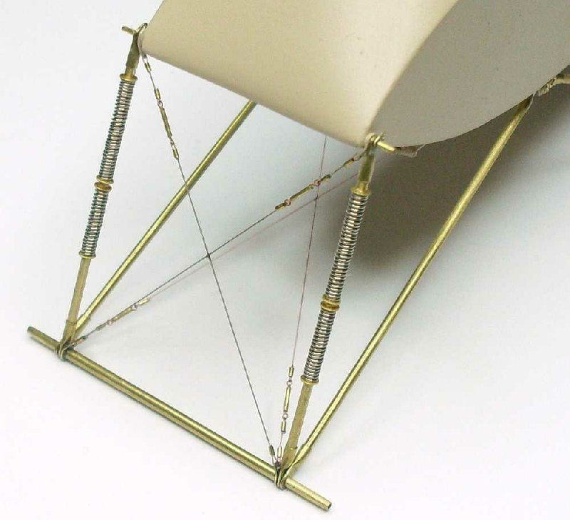
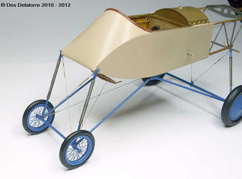
The front portion of the undercarriage is now built but not fixed in position. The main legs are 1.0mm brass tube and on each end is a ferrule made from 1.2mm brass tube. To make the ferrule I flattened one end, I then drilled a 1.0mm hole so it will fit over the axle, I then rounded the flattened end, I cut the ferrule to a short length, the leg of the undercarriage then fits into the ferrule. The hole through the flattened end will vary in size depending on where it is to be fitted. As you can see the ferrules give a very positive fit and even without glue the assembly holds itself together quite well. The machine gun mounting frame is very easily removed and will be put aside to prevent damage whilst the undercarriage is being worked on.
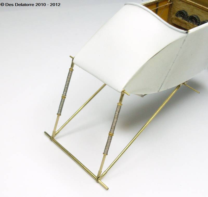
I made the springs from 0.2mm plated copper wire twisted around a length of 1.0mm brass tube. The springs were cut to length and a small brass washer was fitted at the top end, the spring was fitted then another small washer, a third washer was slid onto the tube leaving a small gap then the second spring was fitted, a fourth washer was placed on the bottom, it is all held together with small drops of CA.
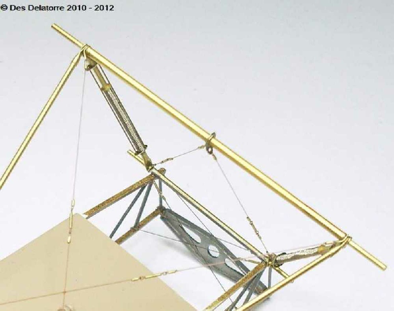
The second photo shows most of the undercarriage components, as you can see I have utilised the small diameter brass tube to a great extent. I have also had to make some small brackets for the rigging line attachments, you will notice two of these are already in place on the axle and the other two, which are sitting loose, will mount on the undercarriage nose attachment point. I made these from thin brass sheet (left over PE frets) with the appropriate size holes drilled through them, I then sanded them to shape with a fine finger nail emery board.

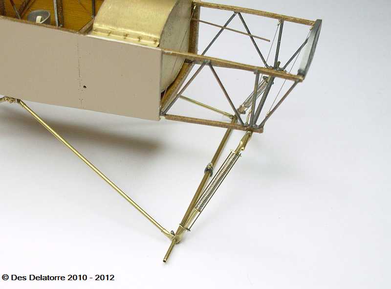
The rear undercarriage is nearly completed, much the same as the front section, I
used small diameter brass tube. The spring arrangement is slightly different in having
two rods running the length of the strut one either side of the spring, these are
mounted to small brackets at the top and bottom which I made from left over PE fret
material. The front undercarriage is now fixed in position and without the rigging
is quite rigid. Using brass tube instead of plastic rod has made the undercarriage
a strong assembly and being such a lanky structure strength is certainly needed.
The brown on the fuselage is Gunze Light Brown acrylic, research has revealed that
a majority of these aircraft had a brown -
A few pictures showing a close-
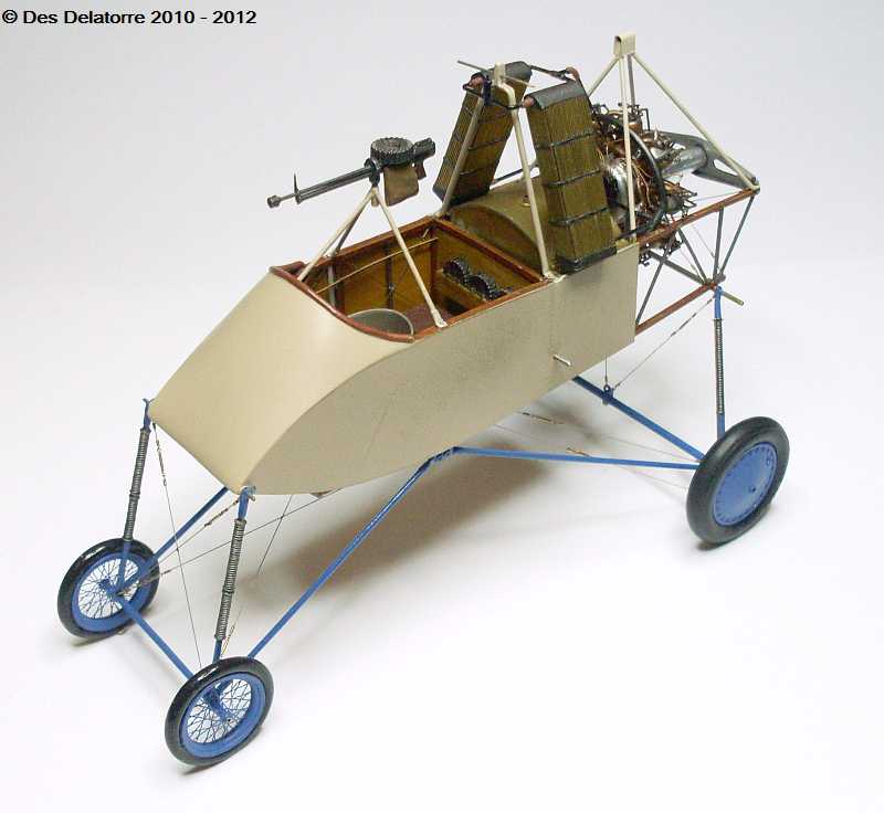
I used the Tom’s ModelWorks spoke wheel PE set to make the front wheels. This is a great set but it does take a fair bit of work to get the PE to conform to the correct domed shape. The spokes are very flimsy and a very easily bent out of shape so extreme care has to be taken when handling the items. Once the spokes are CA’d to the rime it all becomes quite strong and can be handled easily without causing damage. I used a small length of plastic tube for the axle housing.
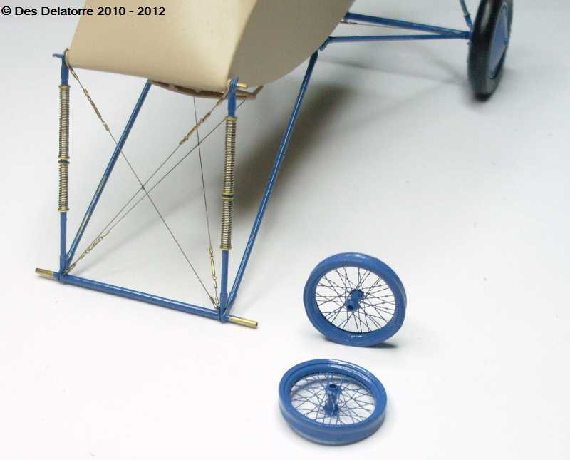
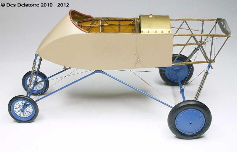
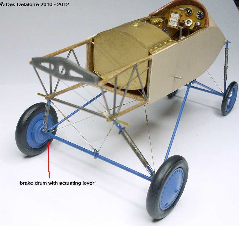
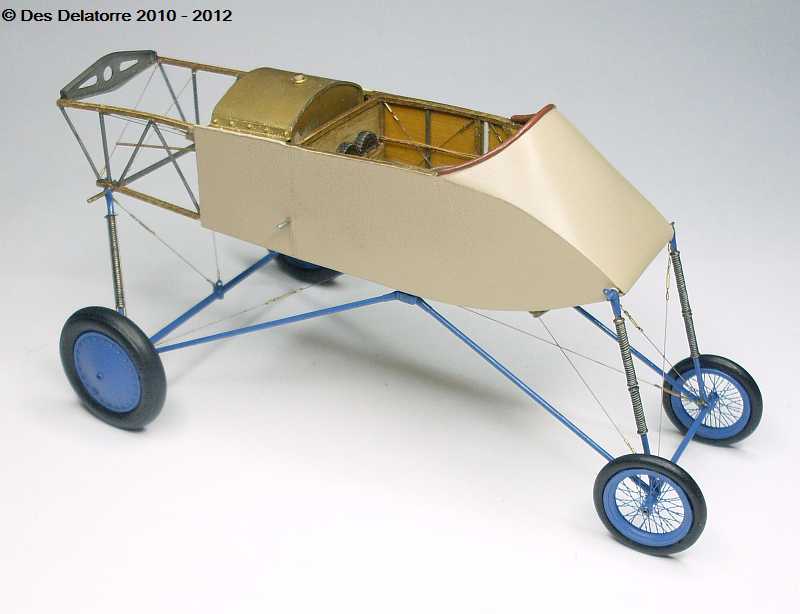
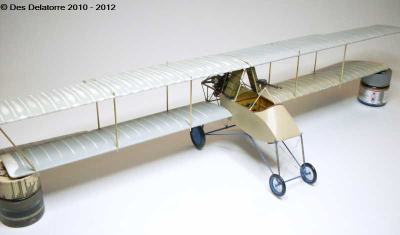
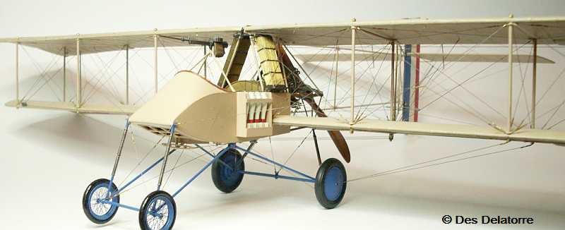
The undercarriage is painted blue to match the directions in the information I have. I made the tyre for the front wheels from 2.4mm plastic tube stripped from an electrical cable, it was cut to length then I used CA to hold it in place, both front and rear tyres are painted with Gunze Tire Black. I also turned up two brake drums for the two back wheels, I also fitted an actuating lever which will be connected by cables to the underside of the fuselage. All the undercarriage rigging is now completed and painted making the whole undercarriage a very strong unit. The wheels are also glued in position, for this I used CA which bonds extremely well to the brass tube axles. It looks a very lanky undercarriage but when the model is placed beside my other models it sits roughly the same height. The wheels and the undercarriage struts have all been sprayed with Humbrol MattCote.
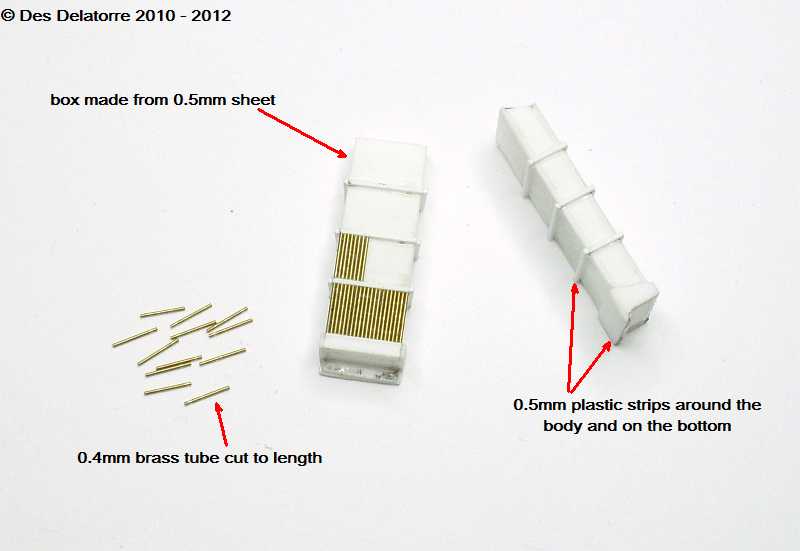
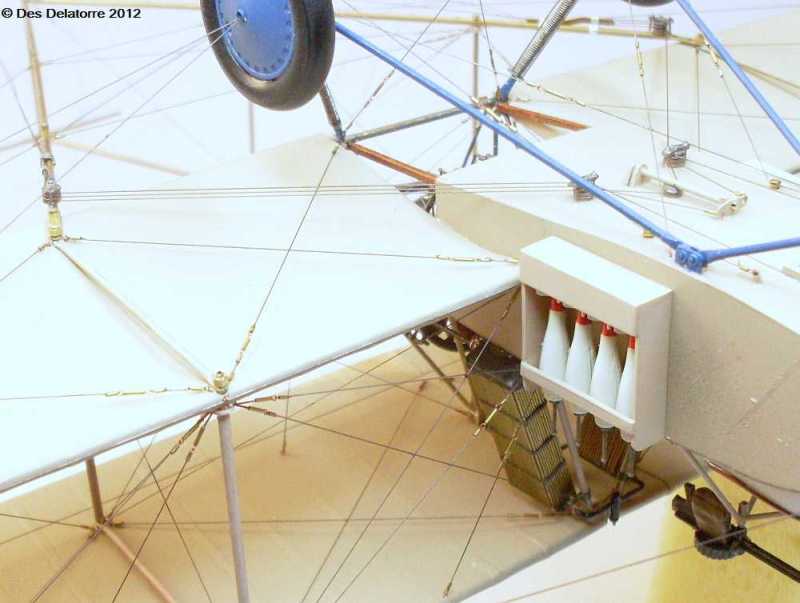
I made the radiators from 0.5mm plastic card, the detailed sections are also from 0.5mm plastic card. I cut 0.4mm brass tube to fit between each of the sections, the photos show the start of this process, it is very time consuming and uses a lot of brass tube.
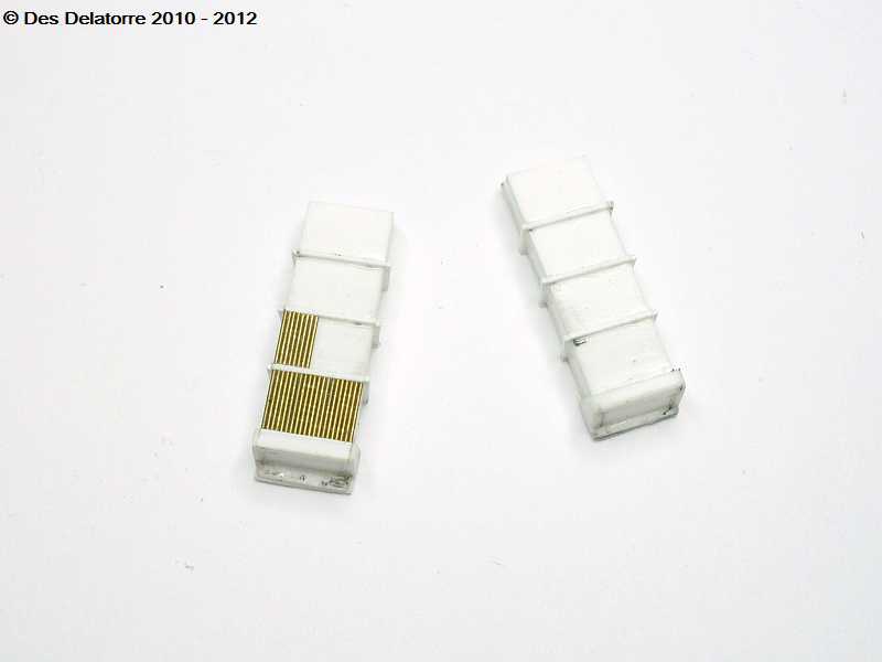
These photos show the near completed radiators, they are just sitting very loose at the moment so are not shown in their correct positions. I ran out of brass tube so I am awaiting the arrival of more stock.
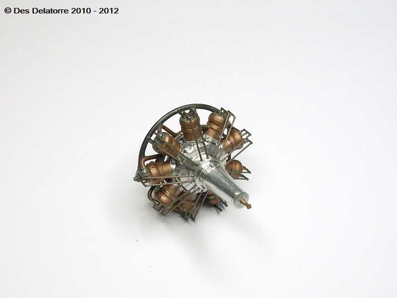
I made the crank case for the Salmson engine from 16.0mm aluminium rod, I turned it down on my new mini lathe to look like photos and drawings I have of the engine. This is just the very basic crank case at the moment, there is still a lot of work to be done, it is a somewhat complex engine design with lots of plumbing and other add on bits and pieces.
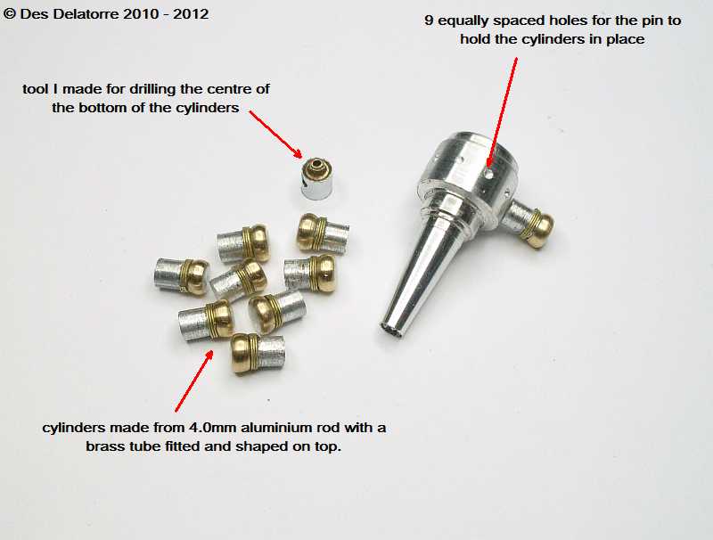
I have made the nine cylinders from 4.0mm aluminium rod, these are the exact right size for the scale, I added brass tube to the top of each cylinder then turned them to shape, I added the three rings of 2.5mm brass wire just below the heads. To drill the nine holes in the crank case I needed a grid, so I made one on my computer drawing program then printed it out, this was then cut out and placed over the crank case and the holes drilled in the appropriate places, this gave me perfect spacing. I also made a small tool to make sure the holes I drill in the bottom of the cylinders are centre, I will be drilling 1.0mm holes in the cylinders and the crank case to take a 1.0mm pin, this, in conjunction with CA will hold the cylinders in place. Before fixing the cylinders I will be drilling the holes where the spark plugs will be fixed, these go in the brass heads, the cylinders will be painted a copper colour to simulate the water jacket. The making of the cylinders has been very time consuming and as they are very small, only 6.75mm long, they are very difficult to handle and hold.
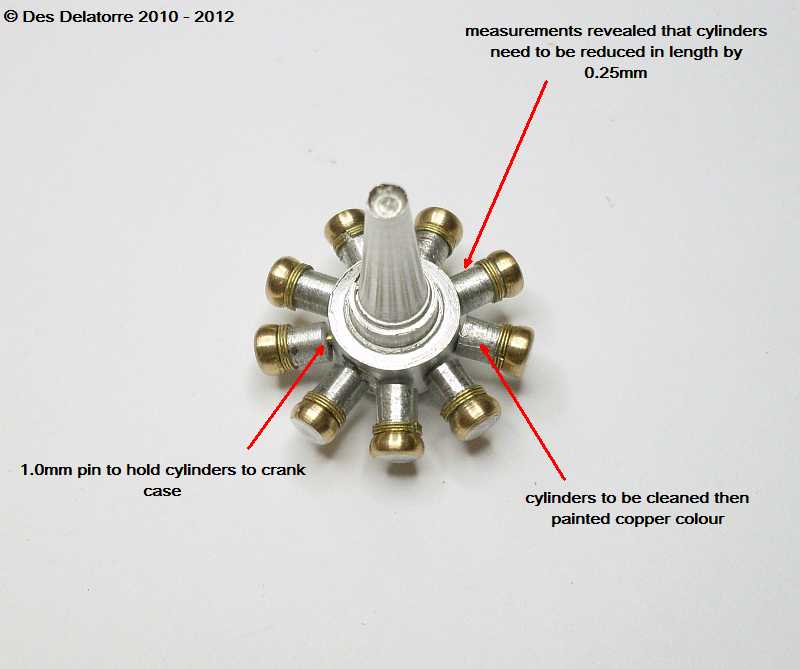
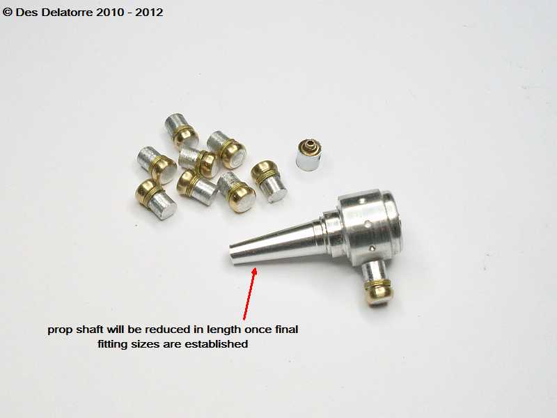
This is a very rough dry fit of the cylinders to the crank case, I am using 1.0mm pins to align the cylinders. Measurements between the overall diameter of the engine and the fuselage frames revealed that I need to reduce the length of the cylinders by a further 0.25mm, the base of each cylinder will need to be shaped to fit the curve of the crank case.
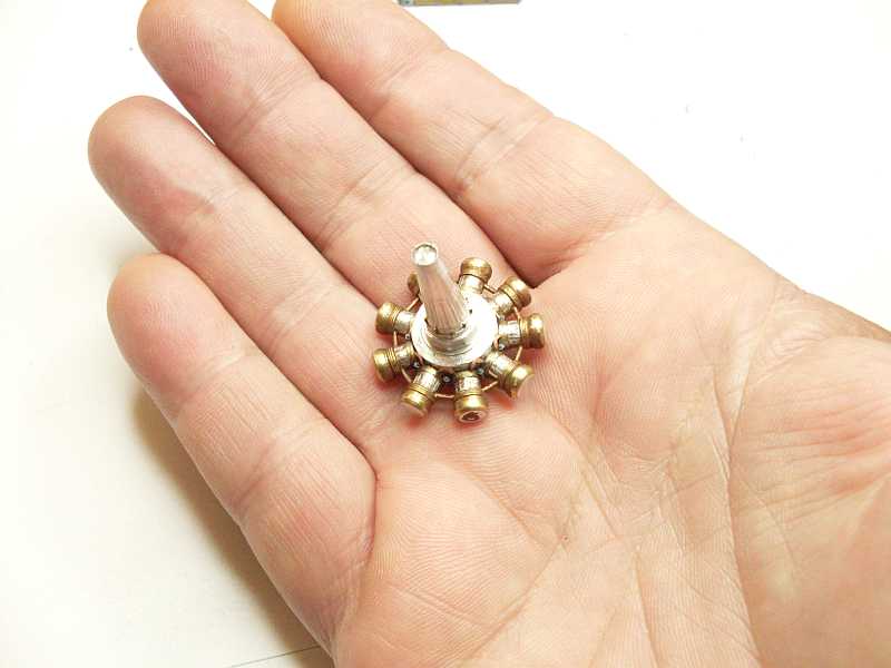
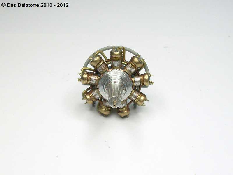
I have recalculated again, I needed to take at least 0.5mm off each cylinder. The hand photo shows the size of this engine and how small the parts are, the cylinders were very awkward to work with. All the cylinders are now glued in position, CA holds them very well. I also fitted the small water pipes that connect each cylinder.
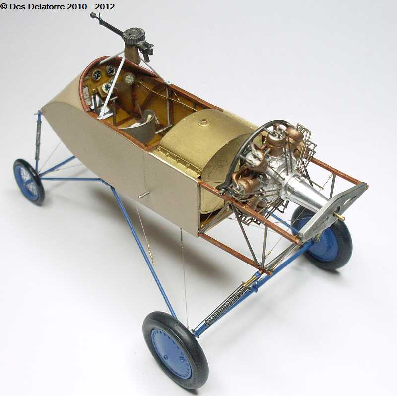
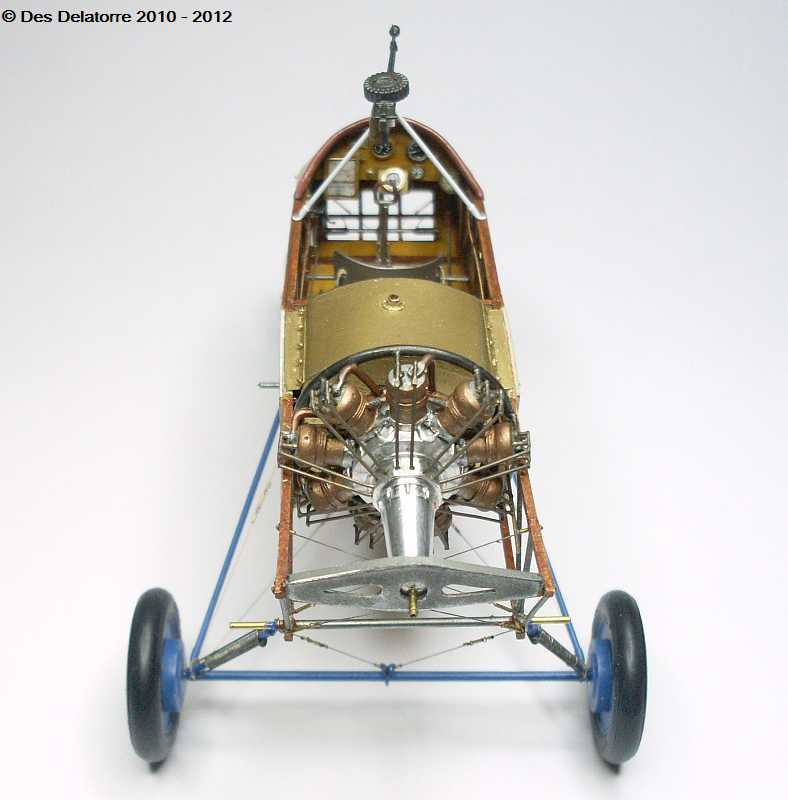
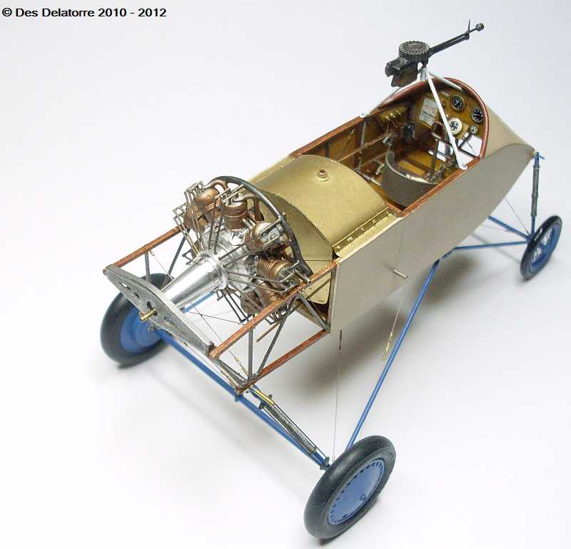
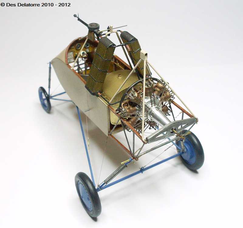
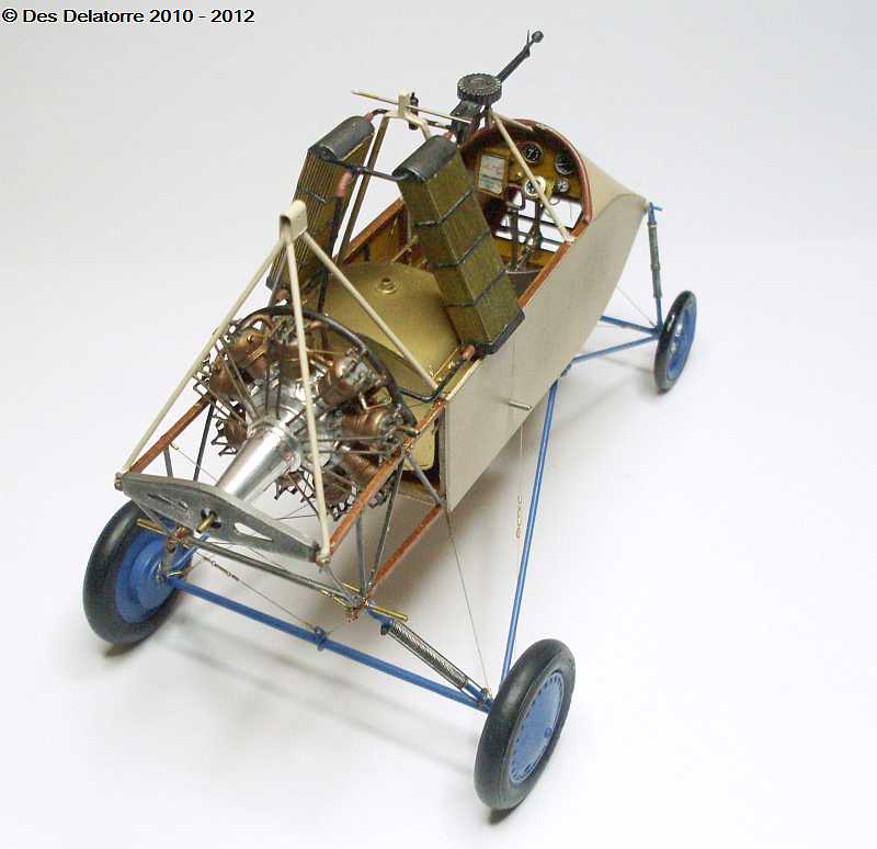
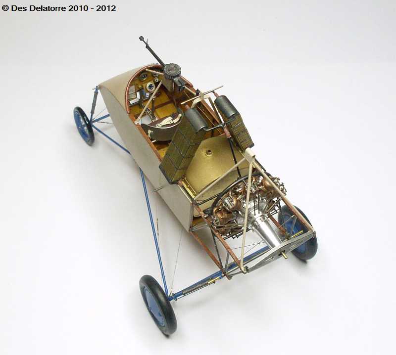
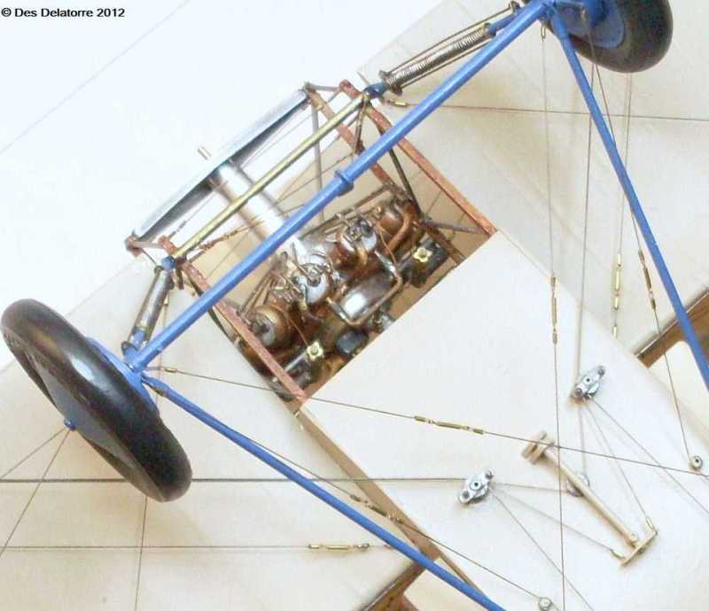
These photos show the engine just sitting for photo purposes, it is in roughly the correct position, the prop shaft will need to be shortened about 5.0mm. I have fitted the inlet manifolds to each cylinder, they are made from 1.0mm brass rod flattened on end that sits on top of the cylinders and a 0.5mm hole drilled through. The manifold itself was made from 1.2mm brass tube formed into a circle the correct size. I have also drill four 0.5mm holes in the top of each cylinder, these holes will take the rocker assemblies. The radiators are also just sitting loose just to give an idea of how things are going to look. The top five cylinders has the exhausts running into a pipe which in turn ran into the inlet manifold, this was done to heat the air/fuel mixture as it tended to freeze. Every task on this engine is very time consuming as most parts are very small and hard to hold. The entire engine and all the plumbing still need to be painted, plus I still need to add the carbies, magnetos, water pipes, electrics, fuel lines, push rods and I need to complete the rocker gear. Hard to see but I have filed the nine flat sections to the cam follower housing ready for the holes to be drilled for the push rods.
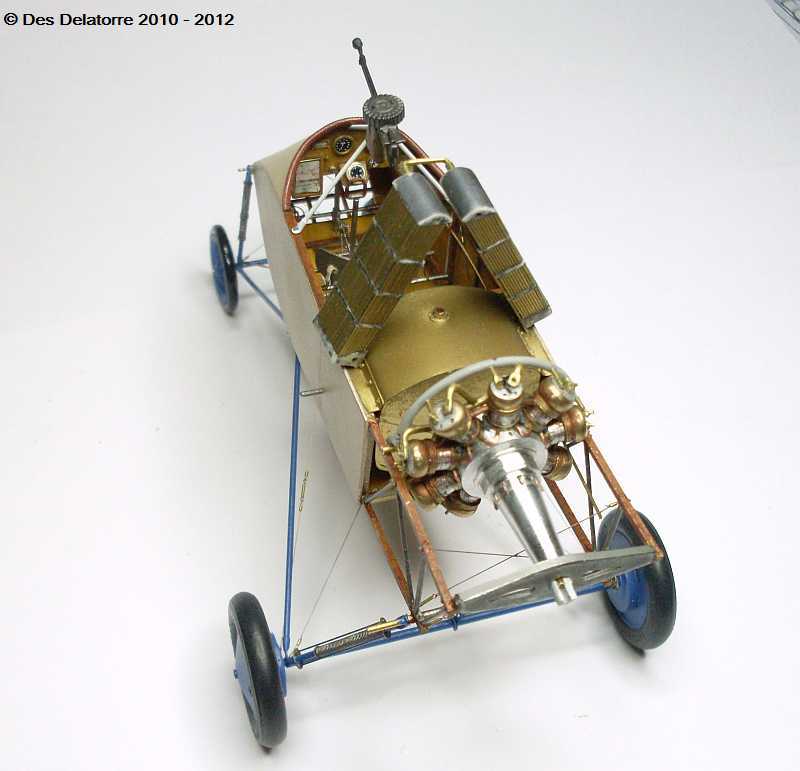
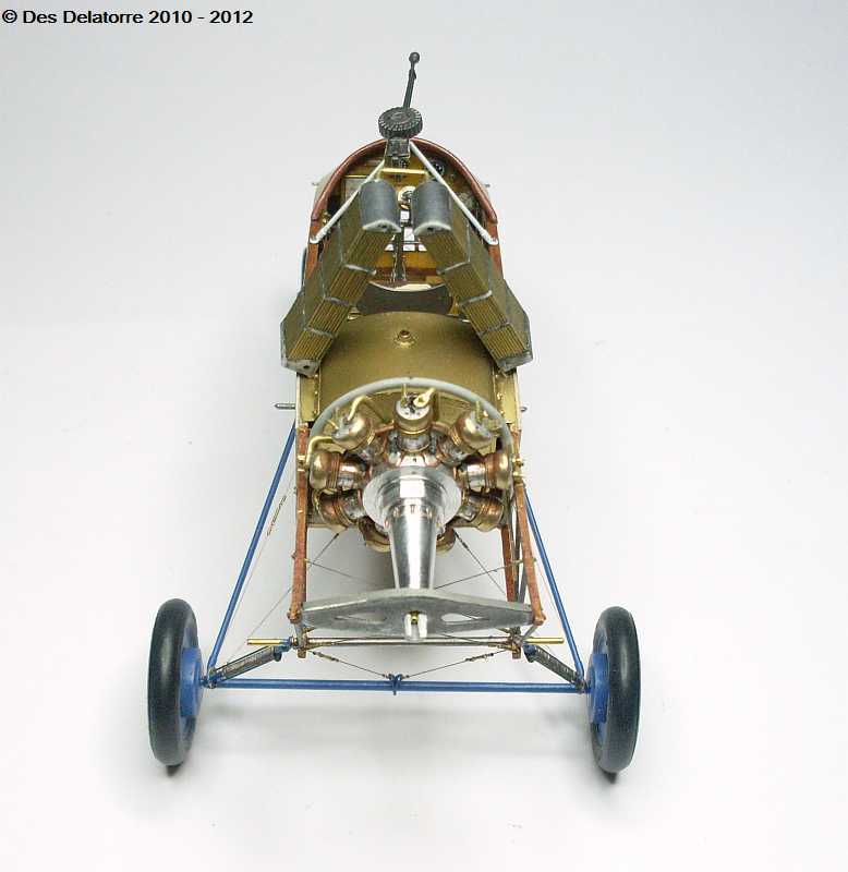
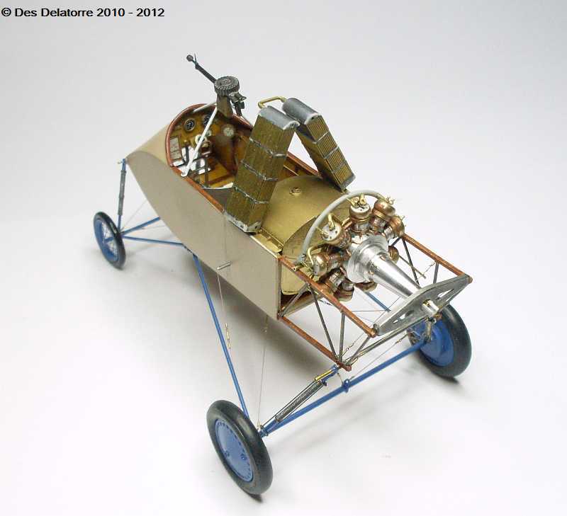

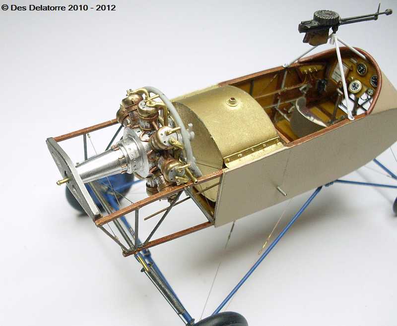
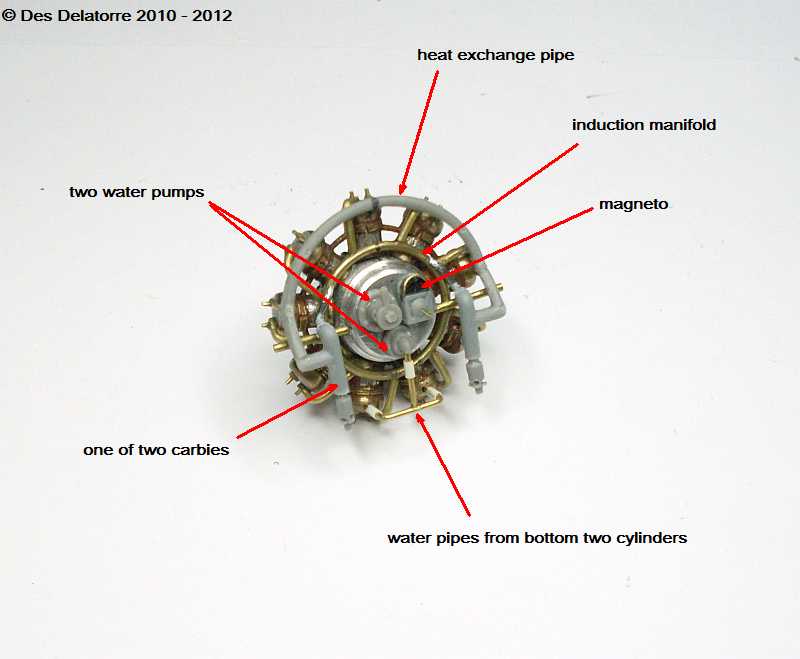

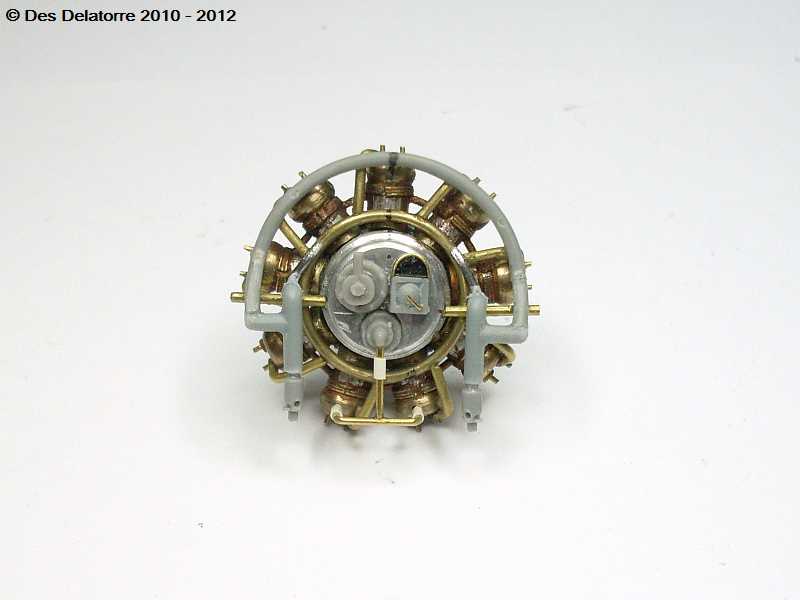
I have added the accessories to the back of the engine, the magneto is fitted ready for the ignition leads, the two water pumps are fitted, the upper one will take the two water pipes from the radiators, the two carburettors are also fitted and are connected to the induction manifold. The heat exchange pipes is also connected to the two carburettors.
I have drilled the 18 x 0.5mm holes in the flat section sections of the cam follower housing, these holes will take the 18 push rods. I also drilled a 0.5mm hole in the side of each cylinder head to take the nine spark plugs, these will not be fitted until the entire engine is painted and near completed. The water pipes at the bottom two cylinders have rubber connection hoses, these were done with small electrical insulating plastic tube from electrical cables.
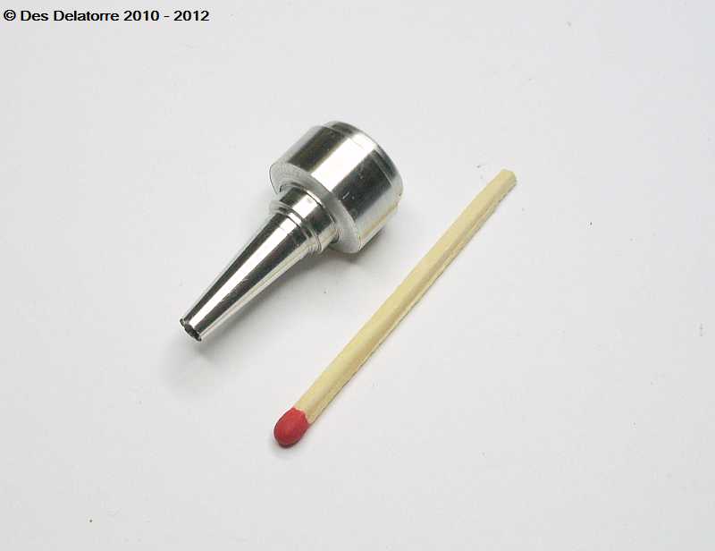
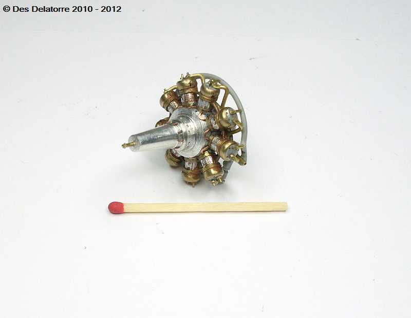
The heat exchange pipe which is the upper most pipe is made from plastic round stock bent to shape and heated so it retains it shape. The obligatory match photo shows comprehensively the small size of this engine hence the difficulty in making it. Naturally, the whole engine requires painting with the accessories and plumbing highlighted, hopefully the cylinders will be painted a copper colour depending on whether I can get a paint brush in between all the plumbing.
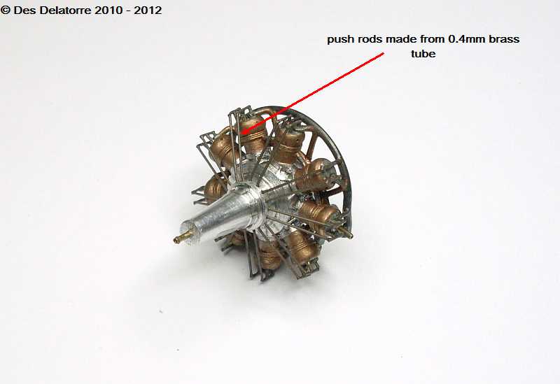
Push rods have been added by using 0.4mm brass tube, these fitted into the 0.5mm holes drilled in the crank case. The rocker assemblies are made from a mix if 0.4mm and 0.5mm brass tube, the outer end of the rocker arm has been flattened, this gives a good surface for the push rods to be glued to. The cylinders have been painted using Mr Metal Color Copper with 30% Mr Metal Color Brass added, this gives me a colour very close to photos I have of the original engine. I have left the crank case as natural aluminium, why paint something that is already the correct colour. I need to add the spark plugs and ignition leads next then the engine is just about done.

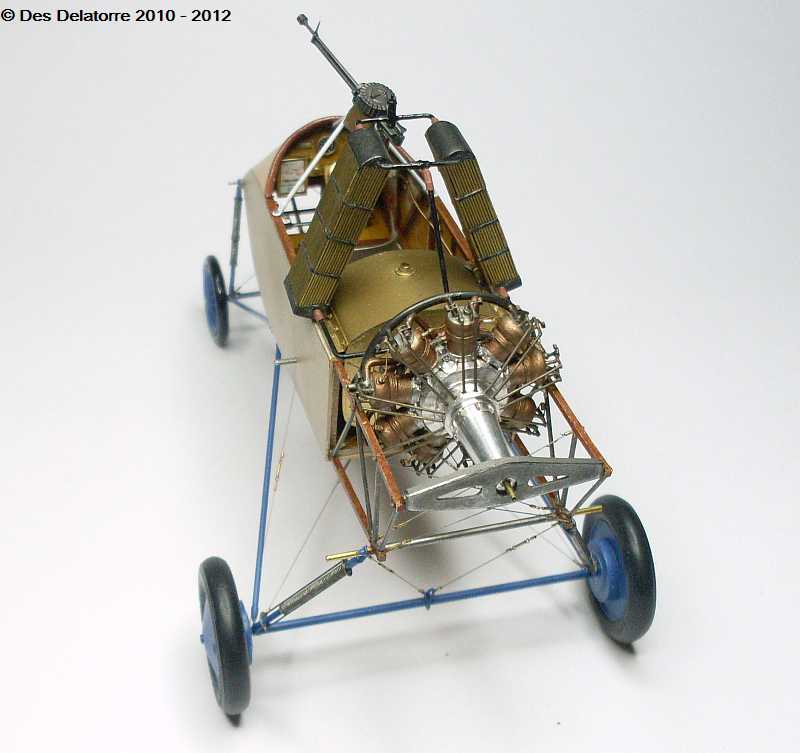
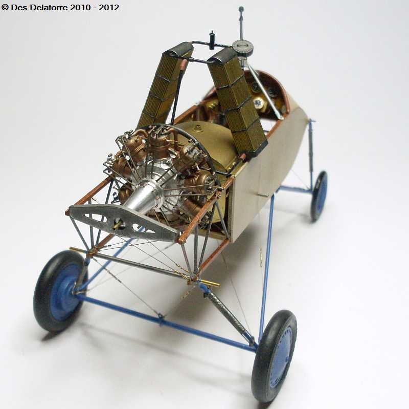
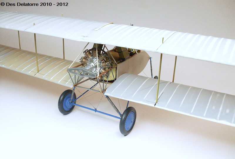
The engine is now finished and fitted to the airframe. I added the 18 valve springs, these are the unusual torsion springs, hard to see in these photos but they are there. I also fitted the 9 spark plugs and wired them to the magneto, I used 0.13mm copper wire for the ignition leads and painted them with Humbrol No.94. The two radiators are also fitted in position and the water pipes have been connected from the radiators to the engine and return, I still need to add the hose clamps to the hose connectors. I am very happy with the way the engine turned out, it looks very similar to photos of an original Salmson radial engine.
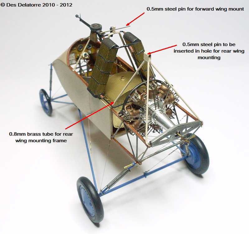
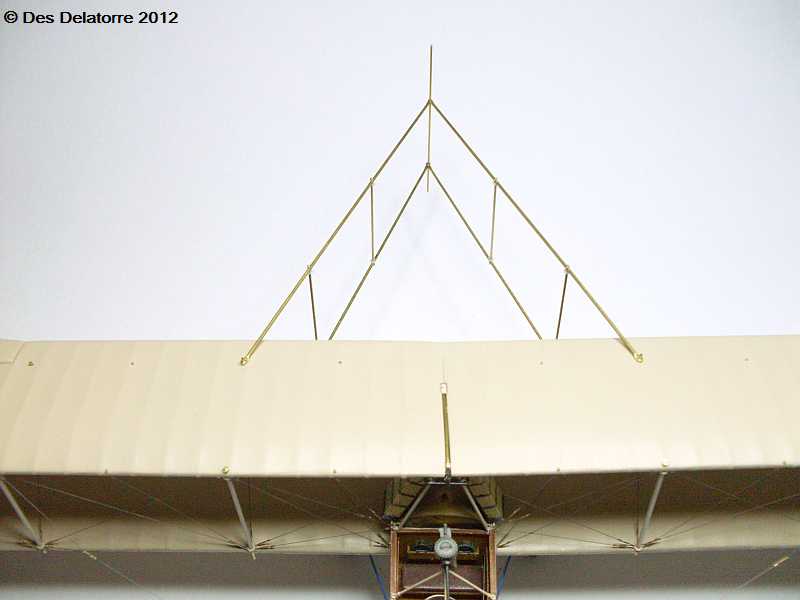
I have made and fitted the forward and rear wing mounting frames. The forward frame is made from 1.0mm brass tube, where the two tubes meet at the top I soldered them together, I drilled a 0.5mm hole and inserted a 0.5mm steel pin (an old drill bit) to act as the wing mounting pin. The rear frame was made from 0.8mm brass tube, the junction point of all four tubes was covered with a piece of brass sheet, a 0.5mm hole was drilled through the sheet, this will take another 0.5mm pin to support the rear of the wing. Both frames are secured to the fuselage frame with Grandt Line bolts and CA. The machine gun and machine gun frame is also now fitted.
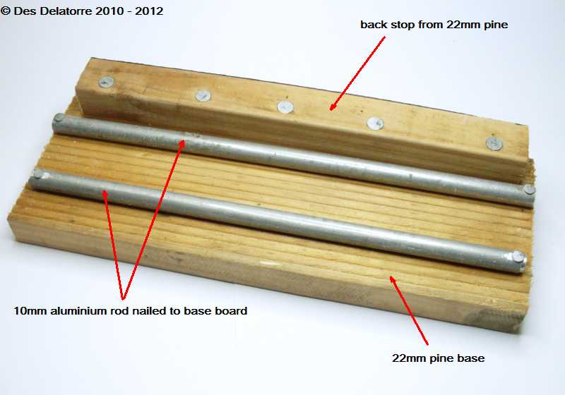
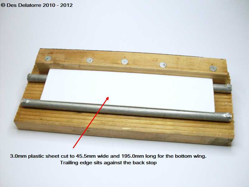
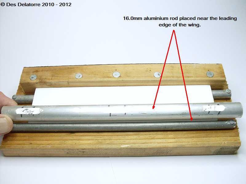
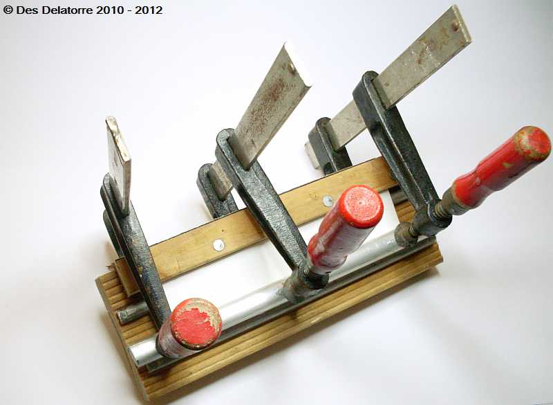
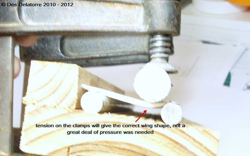
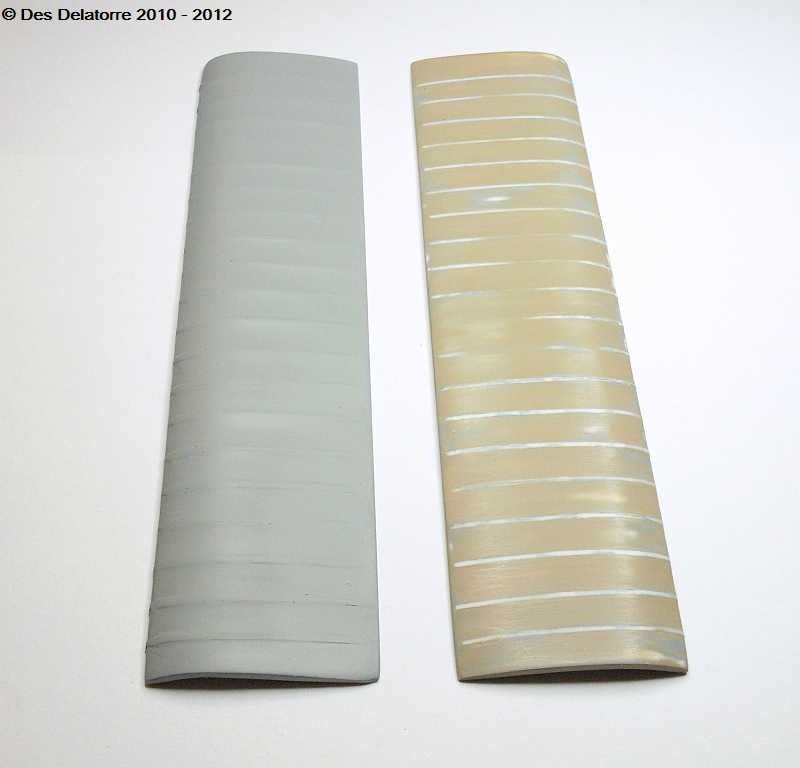
I made a jig so I could bend the wings to the desired shape. I am using 3.0mm plastic card for the wings, this is scored and snapped to the correct size. The wing is then reduced in thickness to 2.5mm in the centre, 2.0mm at the leading edge and 1.5mm at the trailing edge. Once at the correct thickness the wing is placed on the jig with the trailing edge up against the back stop of the jig, the 16.0mm rod id place at the leading edge and the clamps fitted, these are screwed down until the desired wing shape is achieved. A full jug of boiling water is poured over the wing making sure the water covers all parts of the plastic, I then poured cold water over the wing. The clamps are now removed and the wing is now bent to a permanent shape.
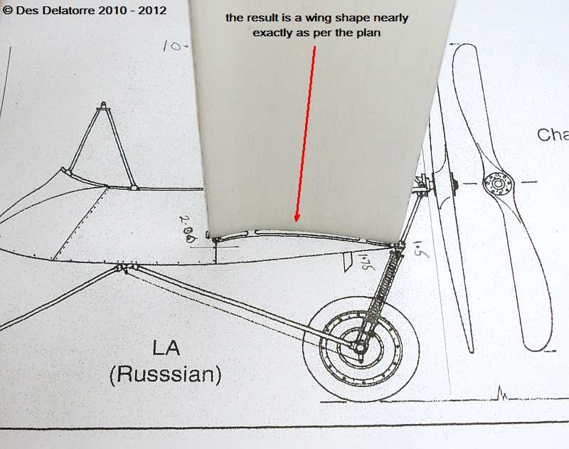
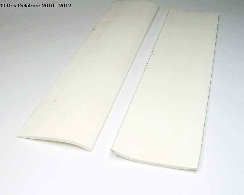
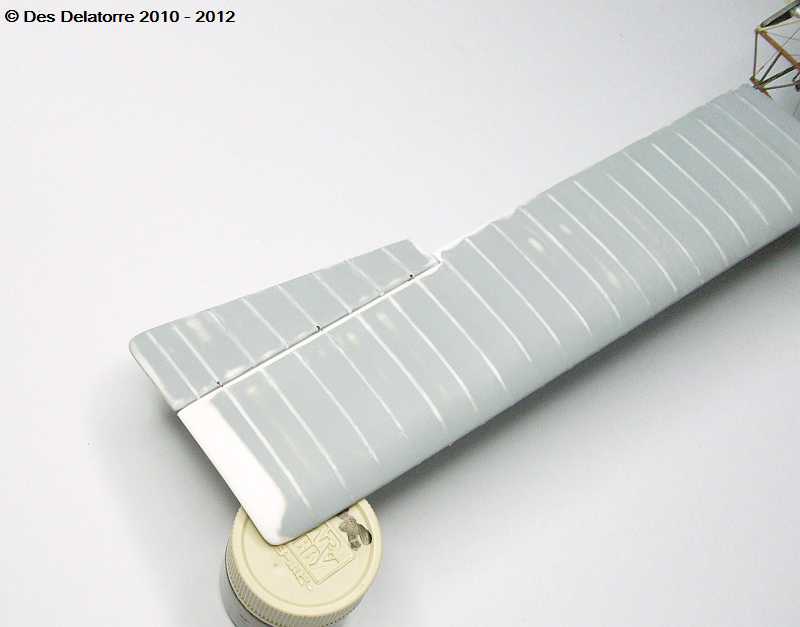
As can been seen in these two photos the wings are now shaped and match the plan near perfect. The leading and trailing edges of the wings need to be rounded and the wing surfaces sanded smooth. Wing ribs will be glued directly to the wing top and bottom surfaces using thin plastic strips, the wing tips also need to be rounded.
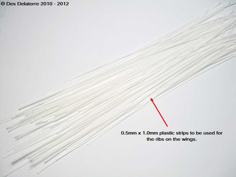
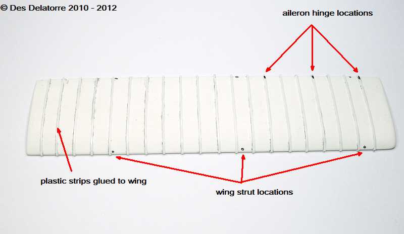
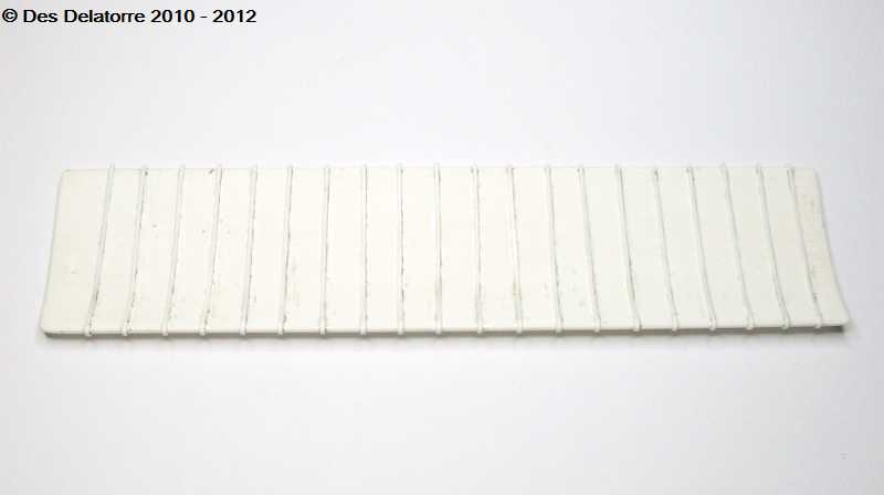
I had some sheets of 0.5mm plastic sheet so I cut them into 0.5mm x 1.0mm strips using a paper cutting guillotine. I sanded the leading and trailing edges of the wing round plus the wing tip. The strip were glued to the top of the wing using plastic glue, once dry the strips were wrapped around the leading edge and glued along the bottom of the wing. The ribs on the bottom of the wing will be sanded down quite considerably, I need to fill between the ribs on the top of the wing then sand it back to give a stretched fabric look over the ribs.
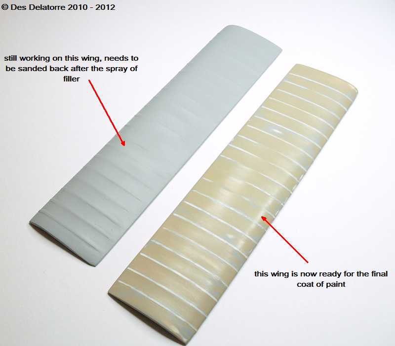
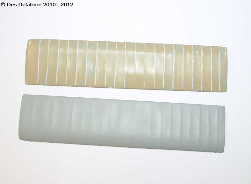
The wings are proving to be very time consuming. The ribs on top of the wings have been sanded back to half their thickness, then layers of filler were applied along the sides of each rib waiting for each layer to dry thoroughly first. Once the required thickness was achieved (three layers did the job) I sanded between the ribs back down to the base plastic, this gave me the scallops between each rib. This process takes a lot of time and a lot of sanding but the end result is pretty good. The underside of the wings have had the ribs sanded back to nearly nothing, just a hint of ribs is all that is necessary. One of the wings is now ready for the final coat of paint, the other one still needs a bit more sanding.
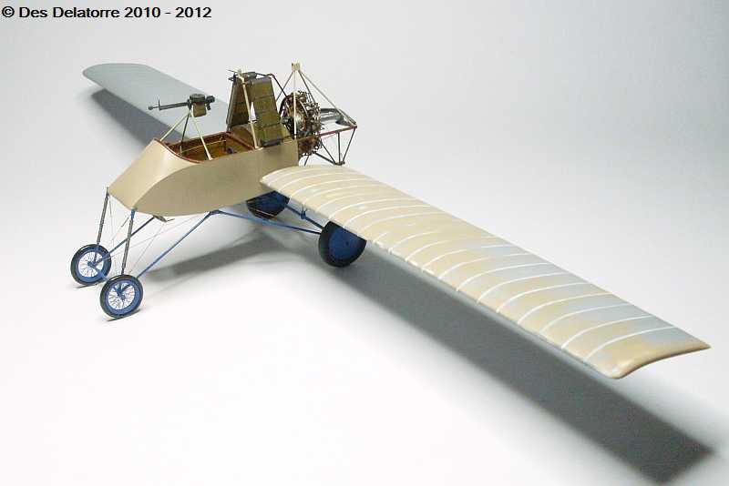
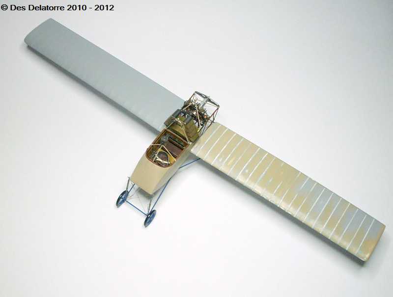
Before I went too much further with the wings I decided to do a trial fit just to make sure everything was right. I drilled four 0.9mm holes into the wing roots, two for the forward mounting pins and two for the rear mounting pins, these holes had to be at least 10.0mm deep so drilling them dead straight was crucial. I gave the pins a slight bend upwards to counteract the weight of the wings. I fitted the two wings and found that they just sat there, nearly dead level and with no glue, I was very surprised at how easy it was to fit the wings.The wings are quite heavy so by the time I put the top wings on it will be a weighty model, luckily the undercarriage is made of brass tube. I will now remove the wings and finish them off.

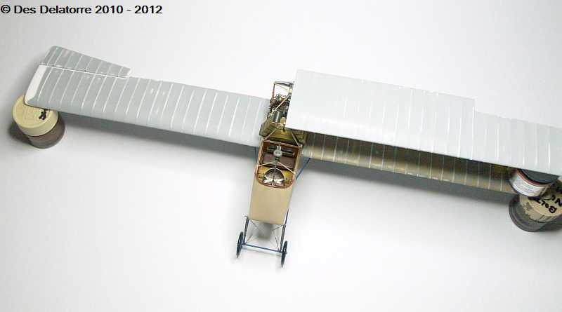
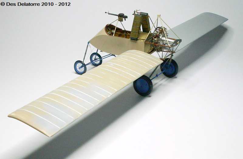
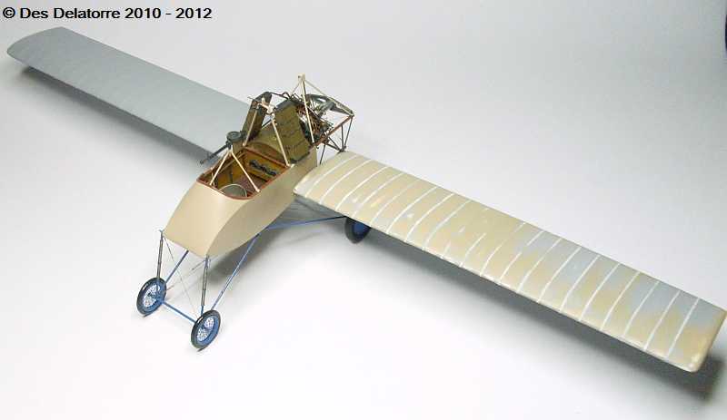
This series of photos show one half of the top wing completed (apart from painting). It is mounted to the forward wing mount with a 0.5mm steel pin (old drill bit) and at the rear with a 0.6mm brass tube, these two mounts are fairly strong but the brunt of the weight will be taken on the wing struts and the rigging. As you can see the top wing is longer than the bottom wing, it is also wider, it was constructed in the same manner as the bottom wings. The struts for this plane will be made from 1.3mm brass tube which is inline with the style of struts used as seen in most of the period photos and reference material I have. There will be 12 struts in total plus a myriad of rigging mounting brackets I also made the two ailerons for the bottom wings, they are now fitted, they are attached to the wing with 0.6mm brass tubes CA’d in place. Overall wing span will be 46cm or 18 inches which makes for quite a large model, and the wings being so long also makes them fairly weighty. Hopefully the second top wing will be ready in a few days.
After a five week long illness I am back at my work bench again. I have made all four (two) wings and fitted the wing ribs, I still need to do a final coat of filler, a light sand then apply the finished colour. Shown here is a temporary fit of the wings with most of the wing struts made. The struts are a simple round section, these are made from 1.3mm brass tube with a 0.9mm brass tube running through the centre. The 1.3mm tube is cut to fit between the two wings giving equal spacing, the 0.9mm tube passes through the top and bottom wing and protrudes past each wing, these will be cut to the appropriate length and a large nut fitted. The inside struts (closest to the fuselage) is where the tail booms will mount, they fit onto the protruding tube above and below the wings again with a large nut to hold it all together. The outboard struts will be angled out at the top to support the tip of the top wing. The struts mount very close to the leading edge so care had to be taken not to break out the leading edge when drilling. Once I have completed making all the struts the wings will be removed and finished off, then fitted permanently. Rigging is going to play a very important role in keeping the wings straight, because of their length the wings are reasonably heavy so will need good support. With the wings in position the centre of gravity is teetering on the back wheels, it doesn’t take much to tip the model backwards.

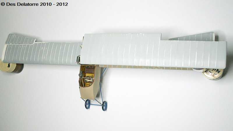
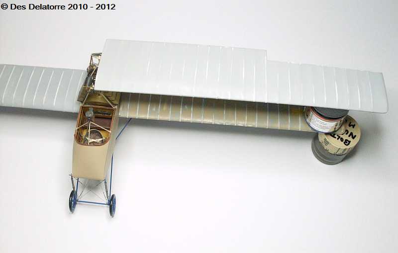
The wings have now been painted and clear coated. These photos show the wings just sitting in position with no glue or any other supports, the wing mounting pins are doing a great job and appear to be quite strong. I have place a strut at each wing tip just to hold the top wing at the correct distance from the bottom wing. I have also added all the rigging anchor points to the fuselage, 18 in total, next job is to fit all the one ended turnbuckles to the wings, there are dozens of them, I made 130 turnbuckles but I don’t think it will be enough. Because of the size of the wings it is hard to get good photos.

The bottom wings are now glued in position, I used plastic glued for the small section where the wings touch the fuselage and then super glue on the pins, it made for a pretty strong join as the wings sit level without support. All the struts are sitting loose on the wings, and the one ended turnbuckles are fitted to both bottom wings, 54 of them. The good thing about the wing struts is that they are a simple round section and they are all the same length, I used 1.3mm brass tube. I am now in the process of fitting all the eyelets to the underside of the top wing.
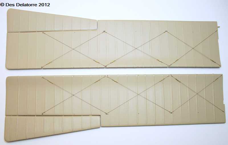
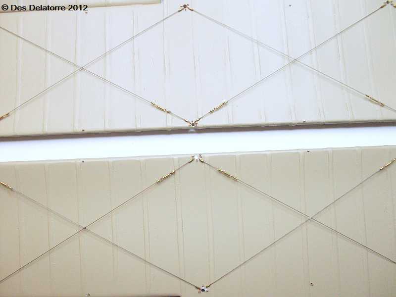
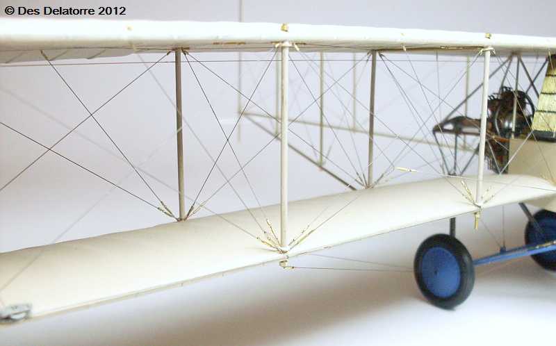
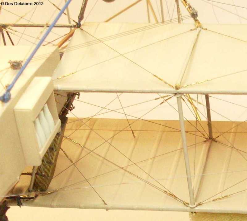
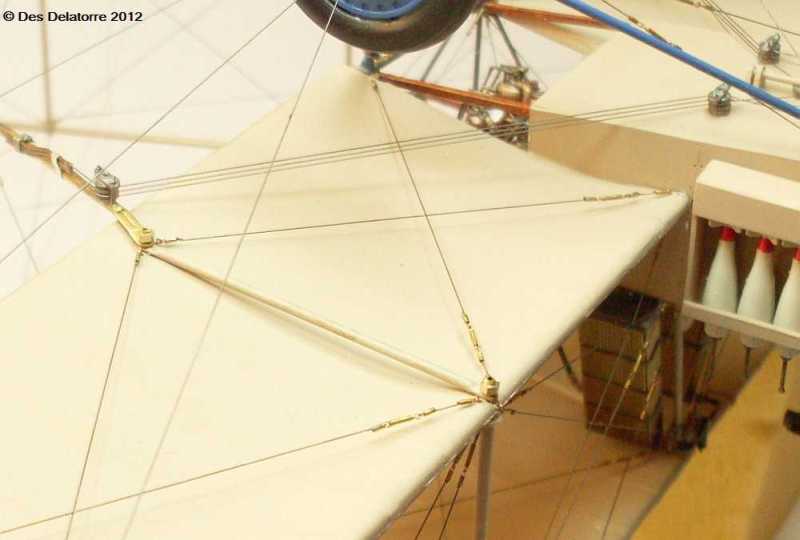
An unusual arrangement on this aircraft is the cross bracing on the underside of
the top wings. I have used 0.12mm monofilament with 0.5mm brass tubes as the little
sleeves, the turnbuckles, which are on every line, are made from 0.5mm brass tube
for the main body and I inserted the small eyelets into each end, the eyelets are
made from twisted 0.13mm copper wire. Very hard to see in these photos but I have
also fitted all the eyelets into the wings ready for the rigging, there are 33 eyelets
on the underside of each top wing. To fit the eyelets into the wings I first drilled
a 0.4mm hole about three parts the way into the wing, holding the eye part of the
eyelet with a pair of pointed tweezers, I dipped the tail of the eyelet into some
super glue then quickly inserted the eyelet into the pre-
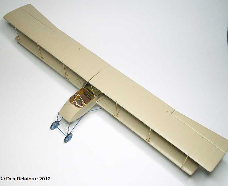
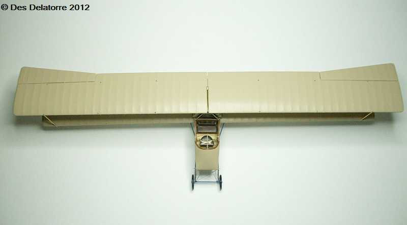
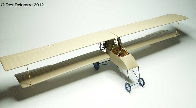
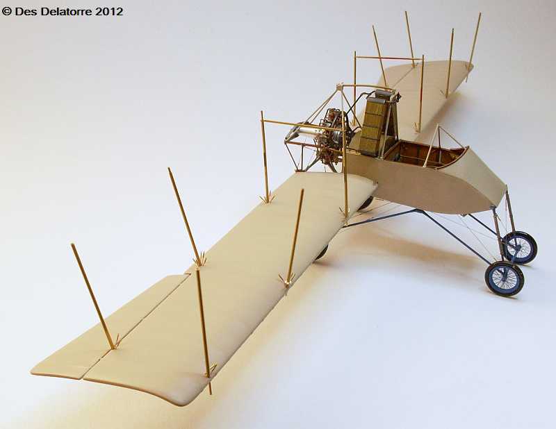
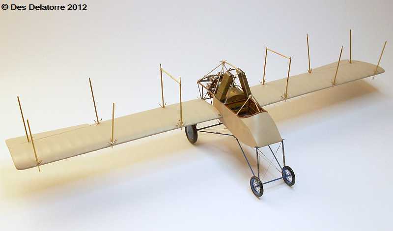
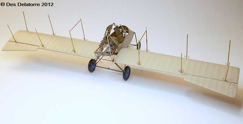
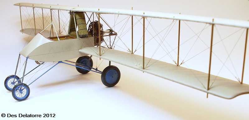
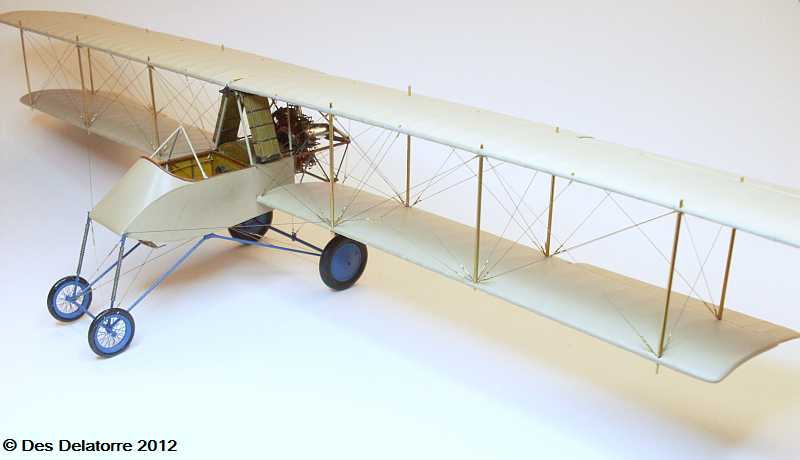
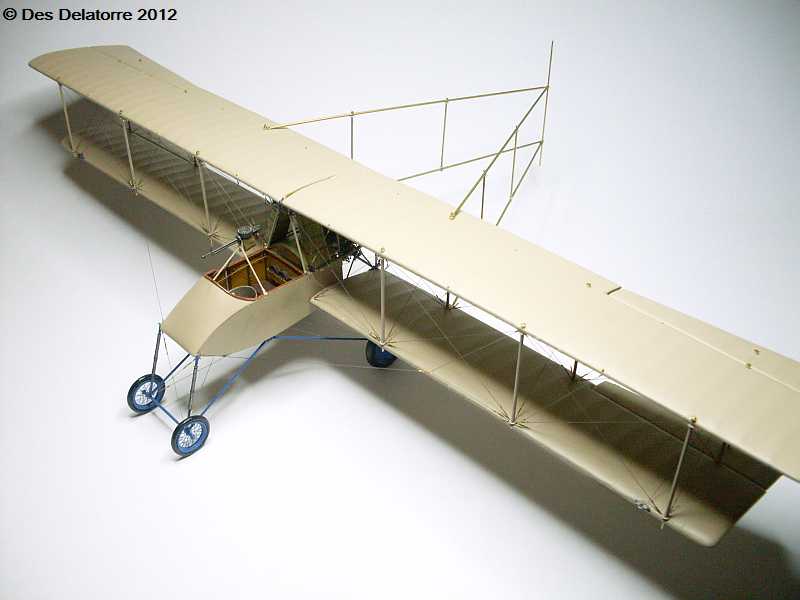
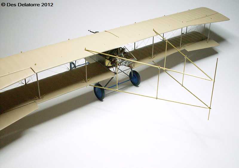
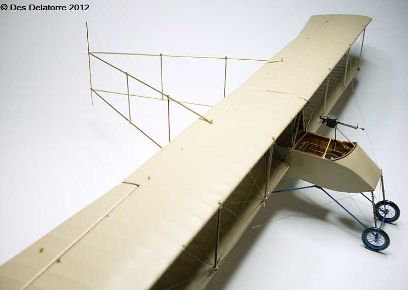
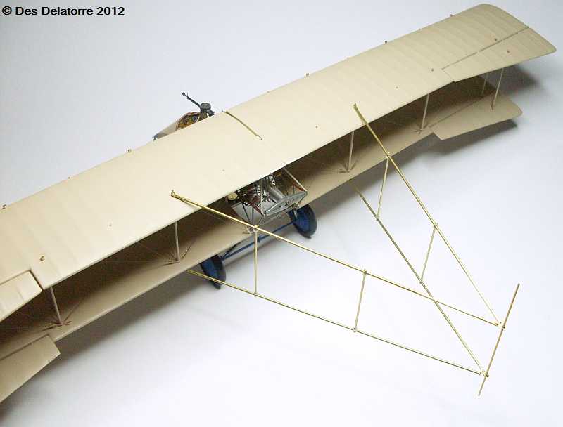
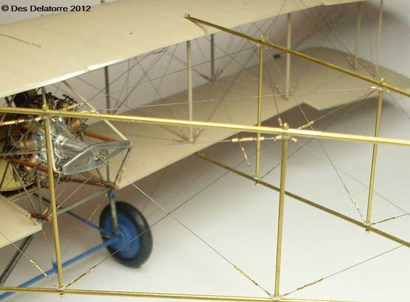
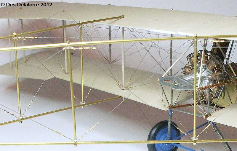
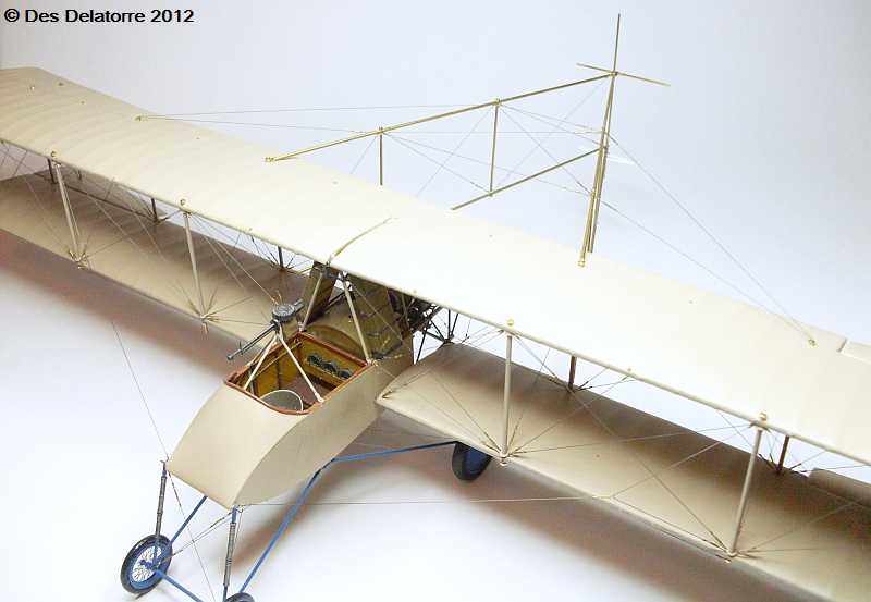
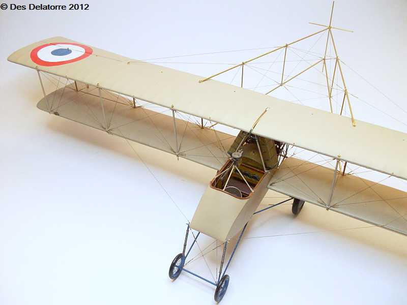
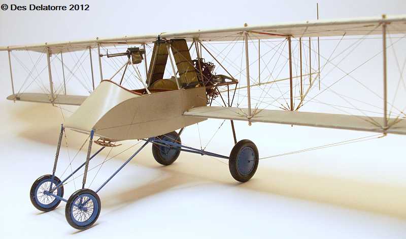
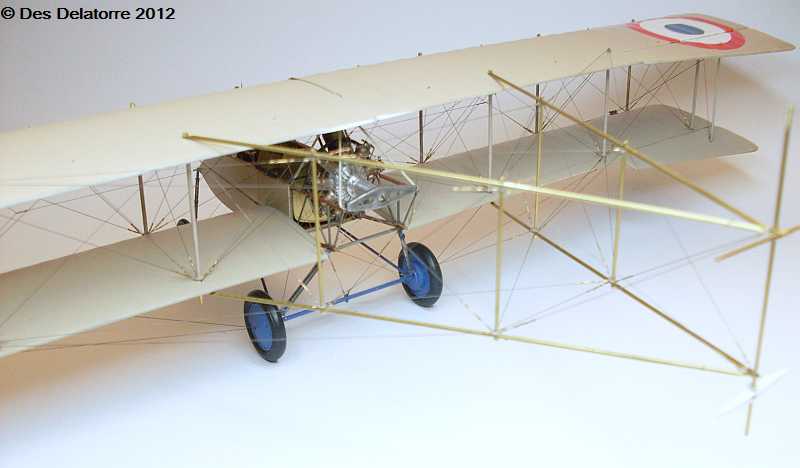
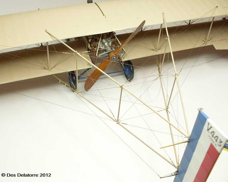
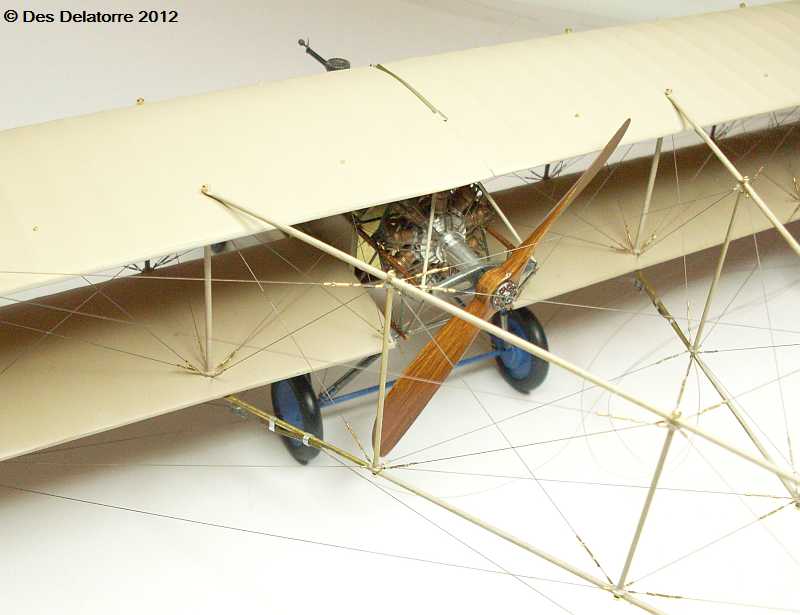
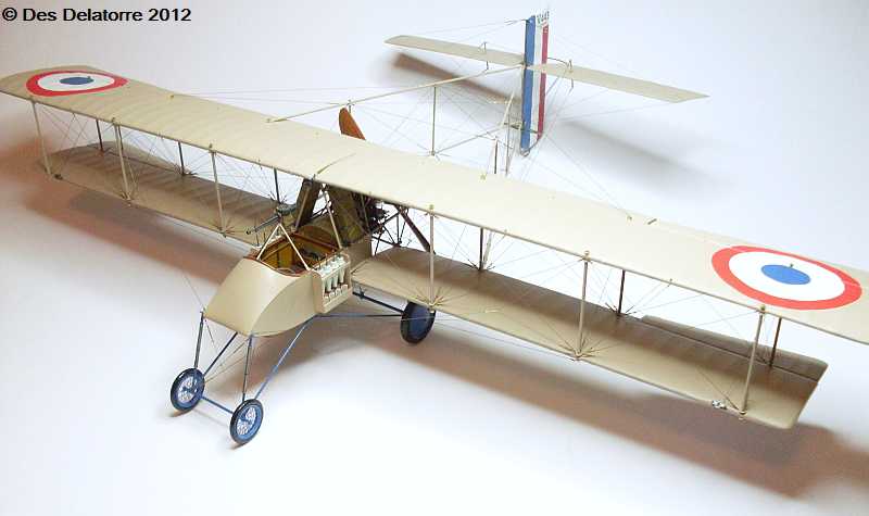
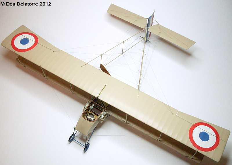
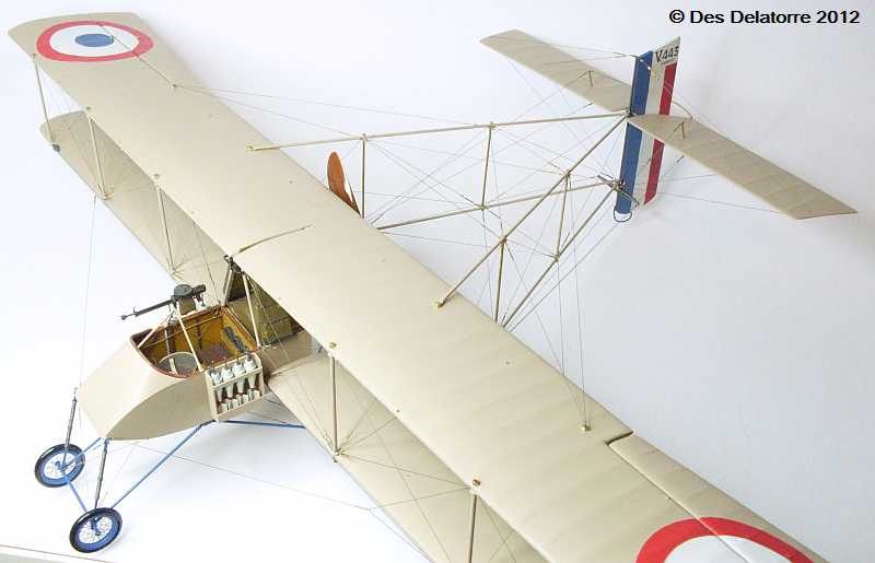
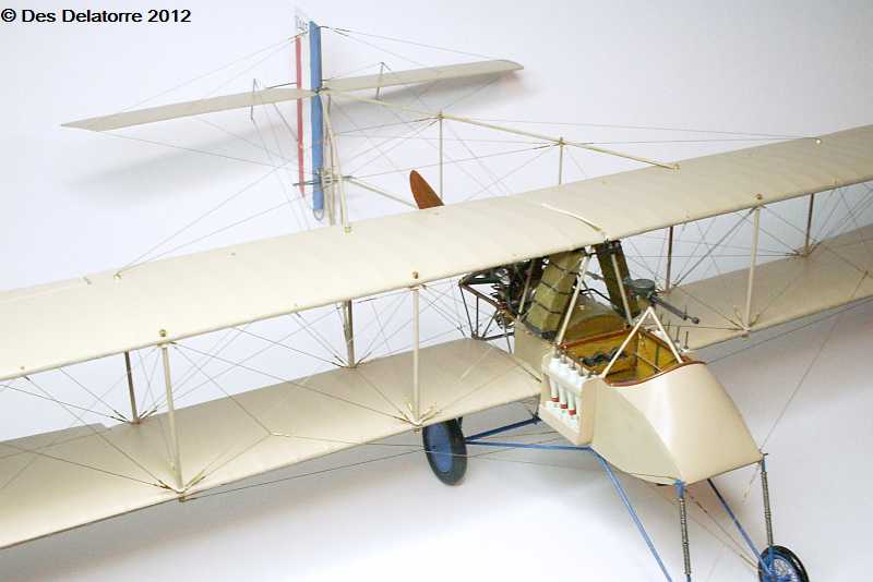
The top wings mounted very easy, the mounting pins proved to be adequate supporting the wings well, with the addition of glue the top wings held without any added support. The struts have also been fitted and glued, the protruding strut ends will be trimmed after the large brass nuts have been fitted. Rigging has also commenced, I am using 0.12mm Maxima Chameleon monofilament, once each line is fitted I paint them with Mr Metal Color Stainless. There will be an enormous amount of rigging on this model so patience will be required throughout the entire process. The photos show the rigging so far, it is only the forward rigging on the first bay, that took a full days work, so it will be a lengthy procedure and one that can’t be rushed. The three photos showing the entire model gives a fair indication of the size of the wings, they are long and heavy.
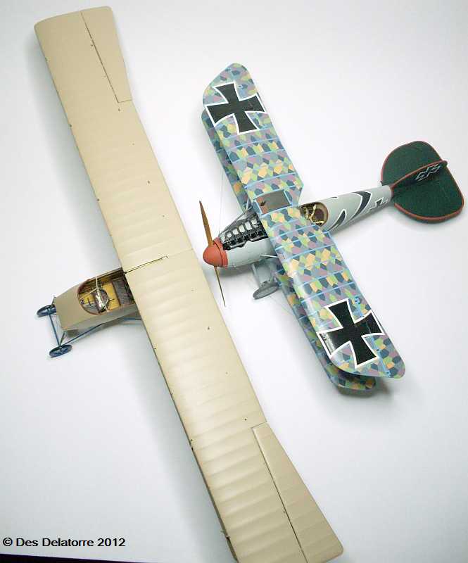
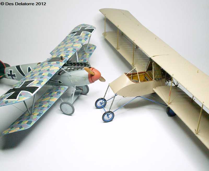
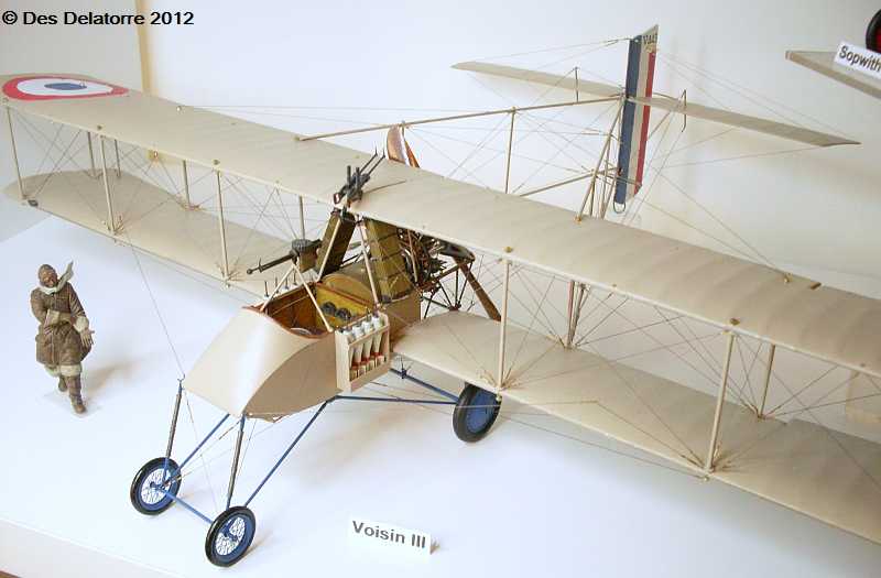
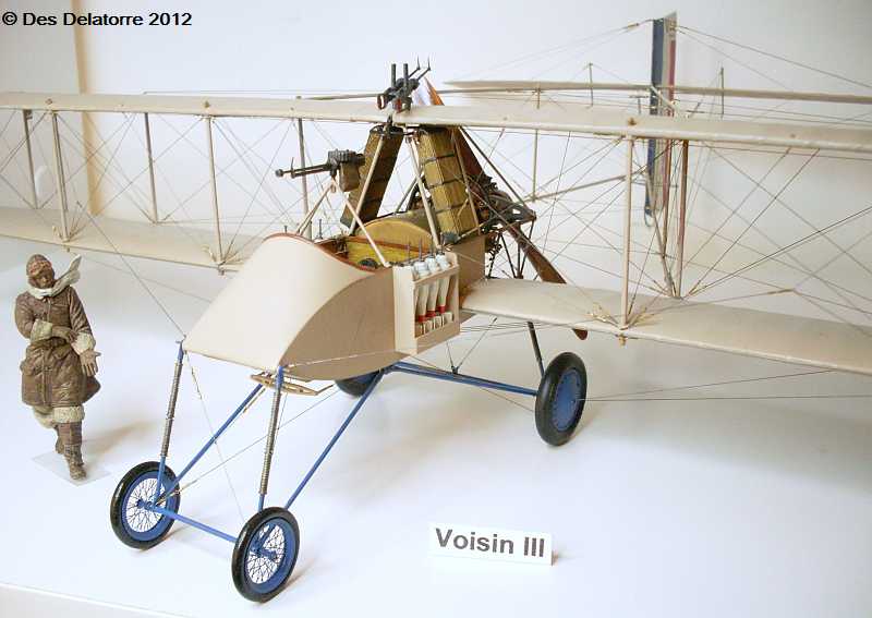
I have had a few people ask me to give a size comparison of the Voisin, so here it is sitting with a Wingnut Wings Albatros of the same scale. The wingspan difference is quite obvious but the actual height of the Voisin is no greater than the Albatros.

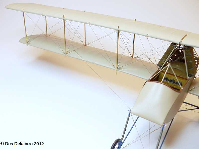
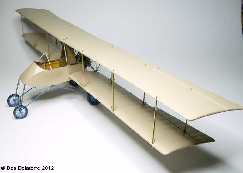
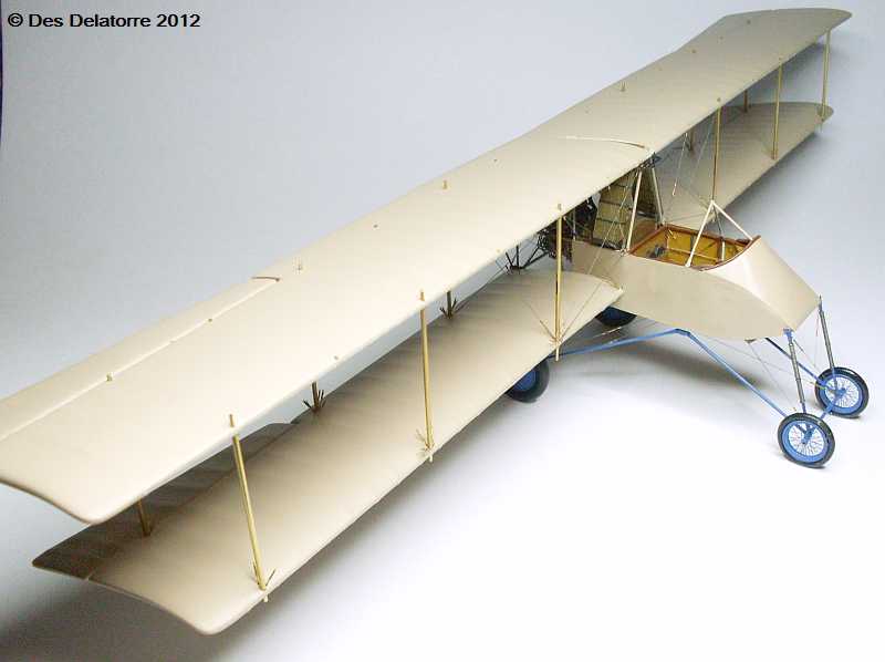
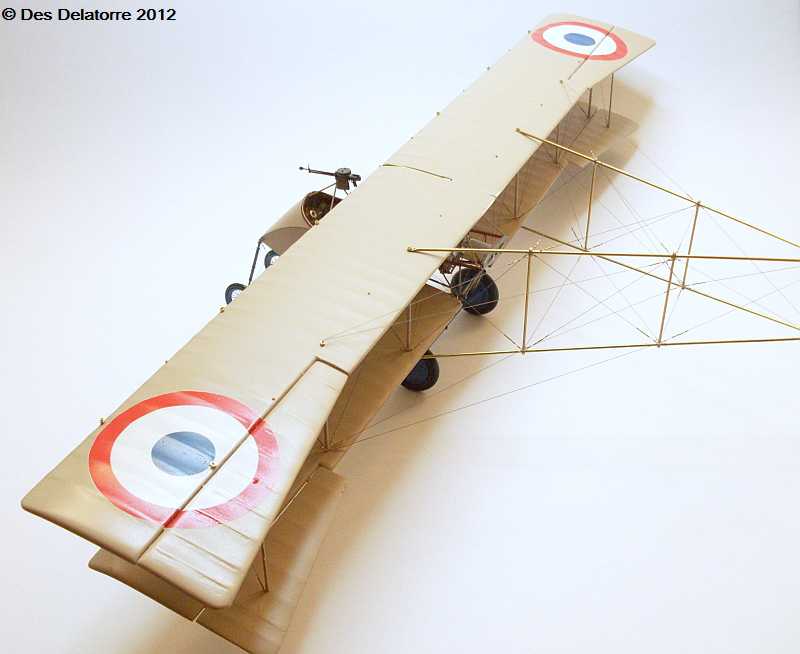
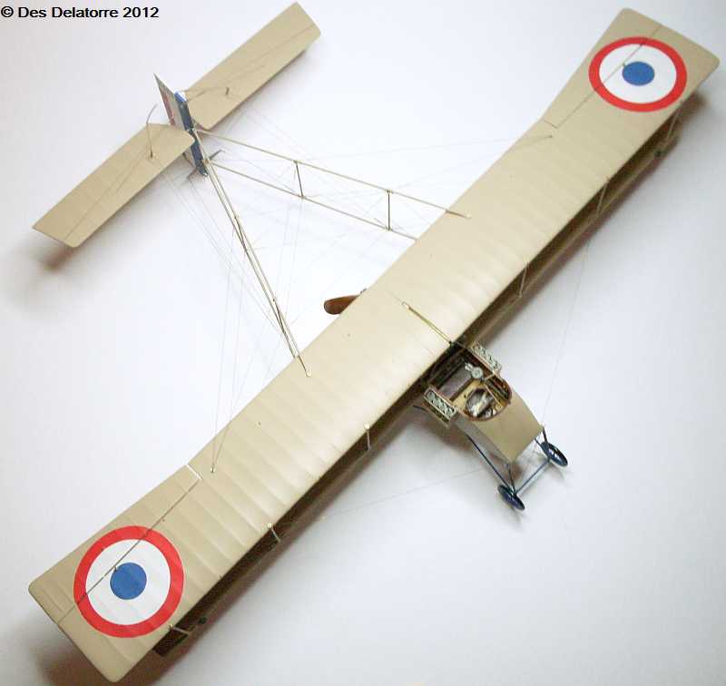
Most of the wing rigging is now completed. I used 0.12mm Maxima Chameleon monofilament line, this is a brilliant fishing line for it’s easy to use qualities, it is very flexible but extremely strong, it can be left as it’s own colour (a brownish colour) or like I have done here paint it with Mr Metal Color Stainless which gives a nice metallic hue. I still need to paint the struts and add the strut plates top and bottom. Most of the control rigging wires and pulleys are visible on top of the wing so they will be added next. The wing assembly is very strong and rigid, the length of the wings when taking photos gives the impression that the wings are a little bent, this is not the case at all, they are dead straight.

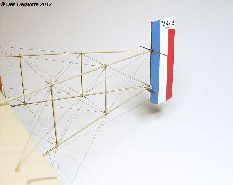
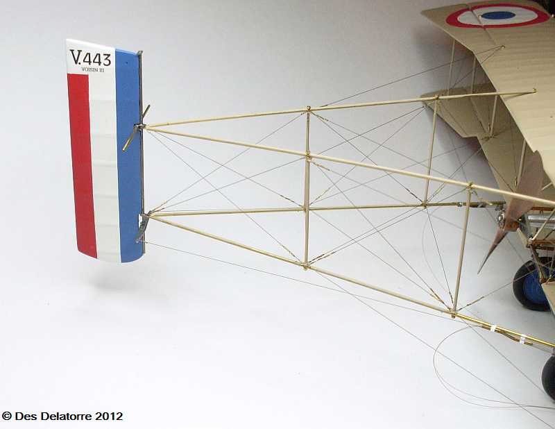
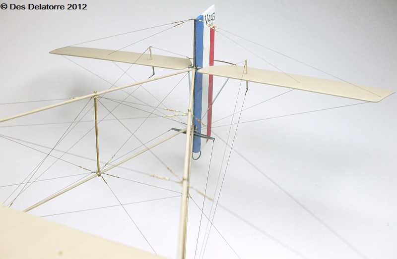
The tail booms are made from 1.2mm brass tube, I flattened the ends and drilled 0.9mm holes to fit over the wing strut extensions. The uprights are made from 0.9mm brass tube with 0.6mm brass tube running through the centre. I drilled 0.6mm holes through the booms then fitted the upright sections, I fitted small brass nuts to the 0.6mm tubes then trimmed them off flush with the nuts. I also punched small plastic circles and they where fitted over the uprights before they where attached to the booms, the plastic circles have a 0.9mm hole in the centre then six 0.3mm holes around the circle to take the rigging wires. The entire tail boom assembly is held together with CA, this adheres to brass extremely well and makes for a very strong structure.


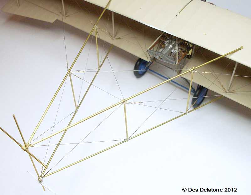

This series of photos show most of the tail boom rigging completed, I still need to do the rigging on the bottom of the booms. I used 0.12mm monofilament, there is a turnbuckle for every line so there is a heap of turnbuckles. The rigging connection to the booms is by way of small discs placed at the top and bottom of each upright. I used 0.3mm plastic card, firstly I punched a 0.96mm hole, then I centred this and punched a disc 2.5mm, this left around 0.75mm of material, into this I drilled six 0.3mm evenly spaced holes around the disc, these holes take the rigging lines. As can be seen in the photos, there is a mass of rigging, but it all certainly helps to strengthen the whole assembly. Before I rigged the booms, I glued two 1.0mm steel rods spanning across the two booms, these held the booms dead straight while I rigged the tail booms, once the rigging was done I removed the two rods and the booms stayed in exactly the correct position, I will do the same on the bottom booms. All the rigging, turnbuckles and small brass sleeves are held together with CA.

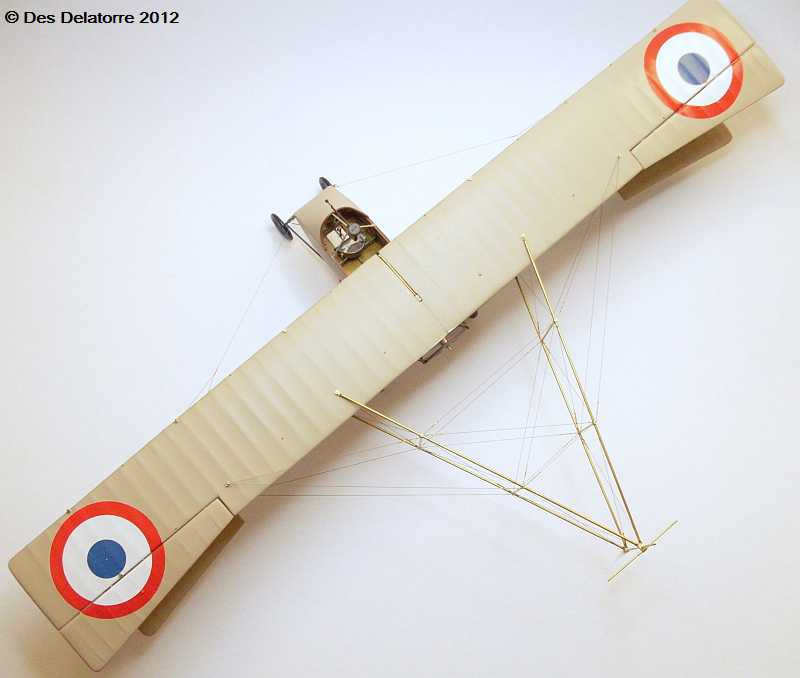
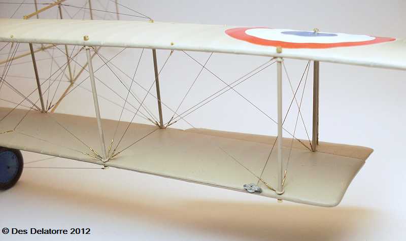
I made my own wing decals using using my drawing program and printed them on white water slide decal paper using an ink jet printer, once dry they were sprayed with clear lacquer. The wing was sprayed with gloss clear then the decals applied, I cut the elevator decal from the main roundel and applied them separately. The roundels are quite large, they are 55mm in diameter (about 2.25 inches). I cut the decals from the sheet using a drafting compass,
I removed the lead part of the compass and fitted a new scalpel blade, this was then run around the outer edge of the red circle, two full rotations of the compass was all that was needed to cut through the decal paper. The last photo shows the pulley which takes the aileron control cable, there is one on each bottom wing plus another one on the top of each of the outer rear struts, there will be more of these pulleys on the underside of the fuselage to take the rudder and elevator control cables. I also completed the tail boom rigging by fitting the last of the rigging to the bottom of the booms, all the rigging has been painted with Mr Metal Color Stainless. It’s a bit hard to see here but there are 28 turnbuckles on the tail boom rigging.
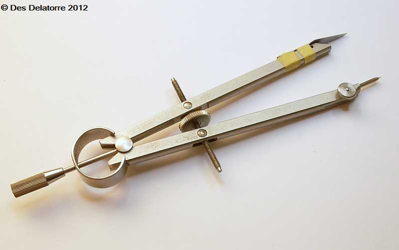
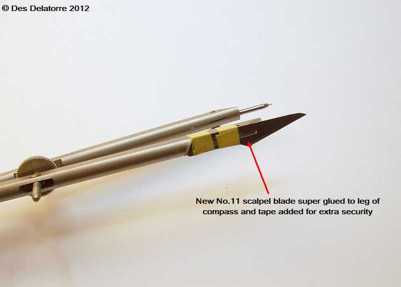

To cut the decals I modified a compass by removing the lead drawing insert, I then super glued a new No. 11 scalpel blade to the leg of the compass making sure the tip if the blade and the point on the centre pin are level. I wrapped some tape around the blade just for a bit of added security. Place the centre pin in the centre of the decal, check by placing the tip of the blade in different positions around the decal, make any adjustments then when you are happy that the pin is centred, push it into the decal and the cutting mat. Holding the compass upright but leaning slightly towards to direction of rotation spin the compass holding pressure on the blade, I found that two complete rotations of the compass will cut through the decal paper quite easily. The small hole in the centre of the decal can very easily be fixed after the decal has been applied by adding a very small dab of the correct colour paint. To revert the compass back to normal simply remove the scalpel blade by sheering it off with a pair of pliers.
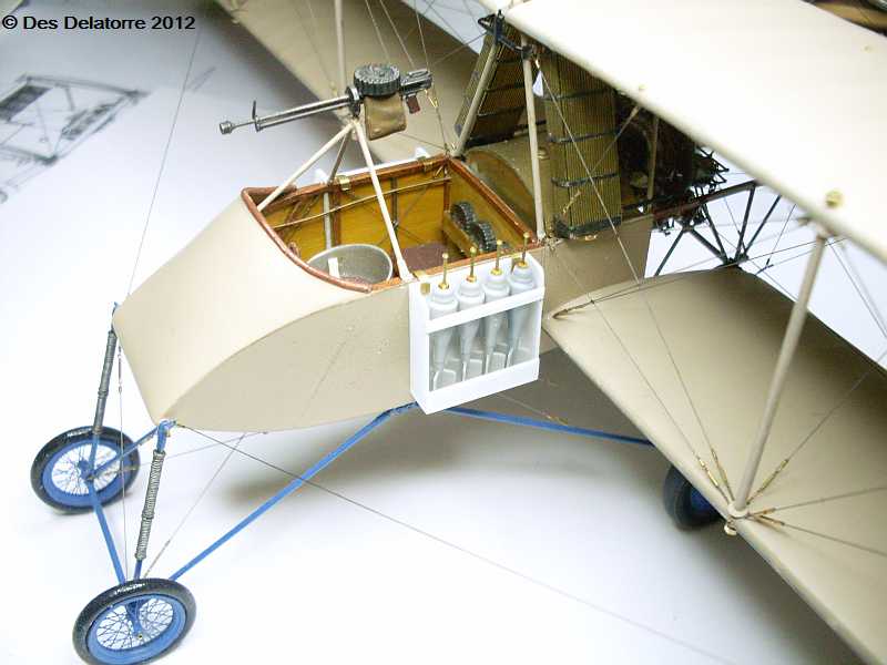
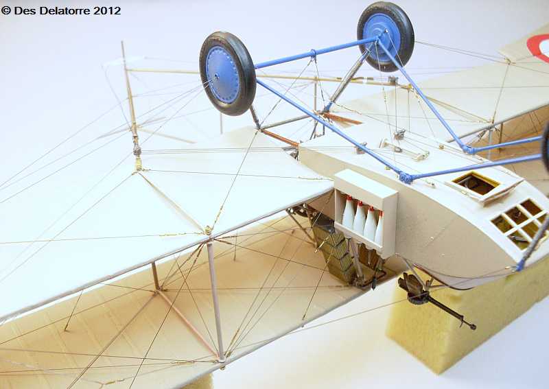
I made the bomb racks from 0.5mm plastic card. The bombs are left over from other kits and are pretty close to the correct size as used on some of the aircraft. The racks are made to suit the size of the bombs and will hang on each side of the fuselage. I added 0.5mm brass tube to the nose of each bomb to coincide with photos of the originals.
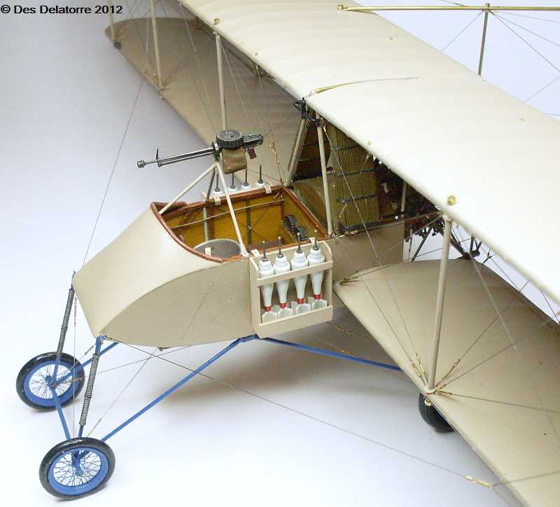
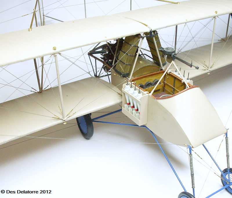
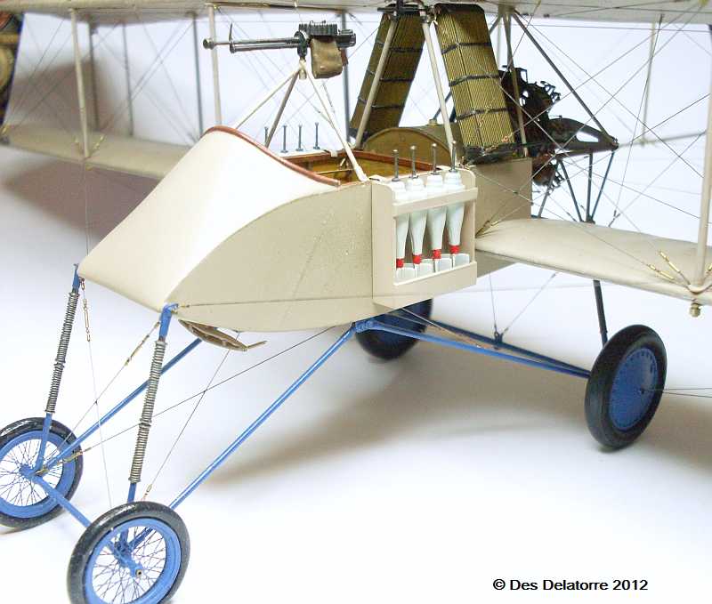
The bombs have been painted with Gunze off white, the tubes are painted with Mr Metal Color stainless and the red band with Humbrol Ferrari Red. The bomb racks are painted with the fuselage colour which is Gunze H321 Light Brown. Once all the paint has cured I will equally space the bombs in each rack and fix them in position. With the racks mounted where they are, it would make it very difficult for the crew to climb aboard.
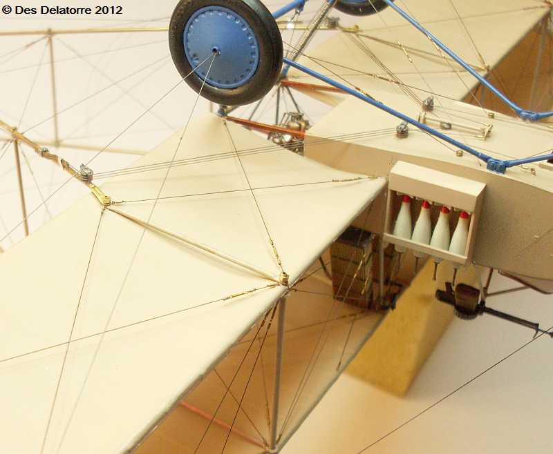
I have completed the under wing and control line rigging. The underside of the bottom wing has the exposed cross bracing wires as with the top wing, each wire has its own individual turnbuckle. I made four triple pulleys to take the three control cables on each side, one for the rudder and two for the elevator. I used 0.3mm plastic card to make the pulleys with a small brass washer between each pulley for separation, a 0.9mm brass tube acts as the axle through the centre. The pulleys which are fitted to the booms have a 0.5mm brass tube through the axle, I drilled a 0.5mm hole into the bottom of the booms and this gave a good anchor point for the two pulleys. The cables needed to be redirected from the pulleys to the sides of the booms so following photos I have I made the cable tubes from 0.4mm brass tube bent to the appropriate shape and attached to the side of the booms. The cables then passed through these tubes and continues back to the rudder and elevators (yet to be fitted and rigged). These photos show the control cable rigging under the fuselage, through the pulleys and back to the booms and tubes, it took quite some time to get this part of the rigging correct.

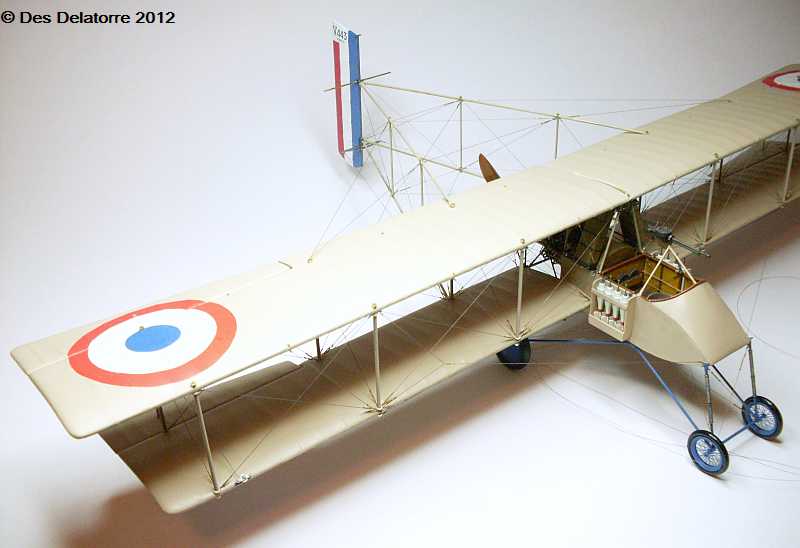
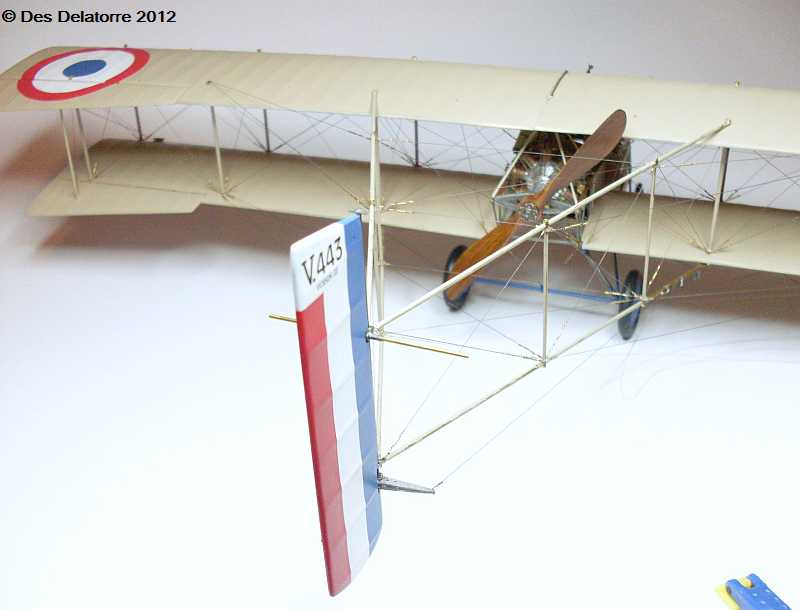
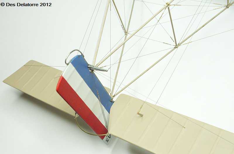
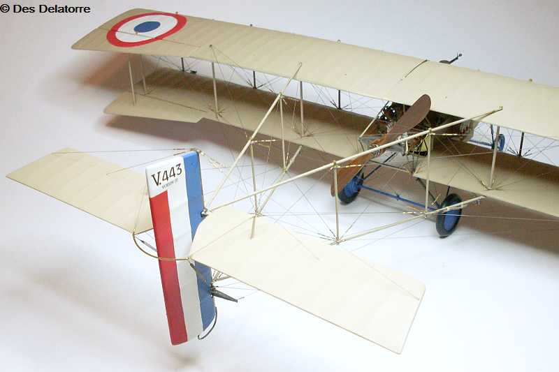
The rudder was made from three layers of 0.5mm plastic card then sanded to shape, the ribs are 0.5mm x 1.0mm strips of plastic card glued to the rudder then sanded down after filler was sprayed over them. I painted the rudder with Humbrol gloss white, then applied the blue stripe, Humbrol No.14 French Blue, and the red stripe with Humbrol No.220 Ferrari Red, it was masked off using 6.0mm Tamiya masking tape. The serial number decals were made with my drawing program then printed onto decal paper with my ink jet printer. Once everything was dry the rudder was given a coat of matt clear. I glued the rudder onto the rudder post using CA, the post was then painted with Mr Metal Color Stainless, I also painted the rudder control horn with the stainless paint. The propeller is also now fitted, it was base coated with Gunze sail color then the wood colour was added using oil paints, once dry it was sprayed with a gloss clear, the propeller hub has been painted with the stainless paint and highly buffed. At this point the C of G is now on a very fine balance of tipping backward, the slightest touch on the tail tips the model backwards.
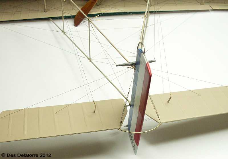
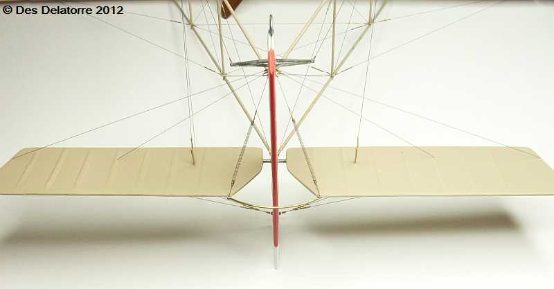
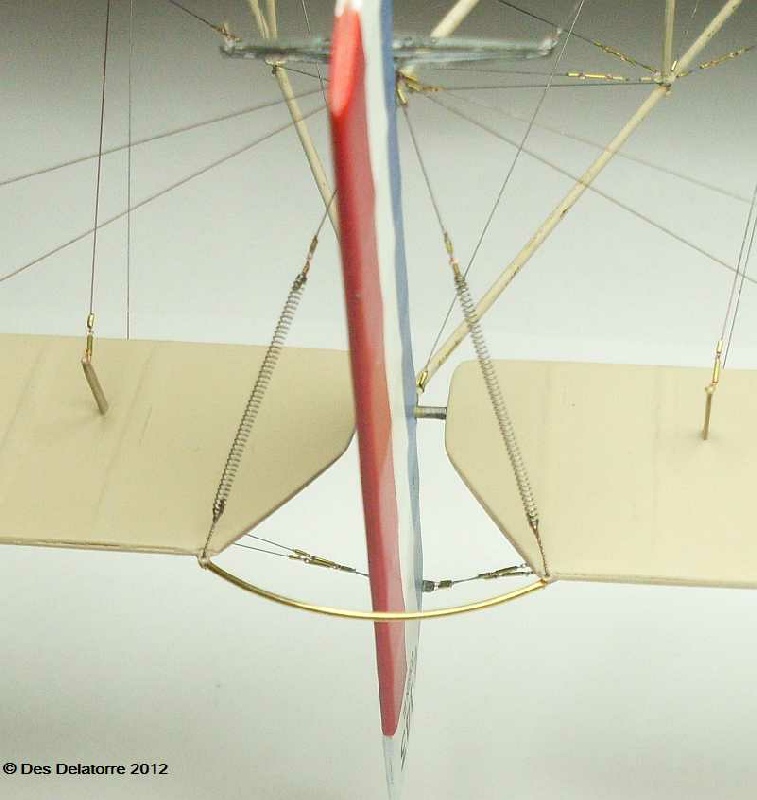
These photos show the underside of the tail plane with the rigging all attached. There is the unusual arrangement of long springs connected to the rear of each elevator then connected to the lower end of the rudder post, the purpose of this is a bit unsure. Rigging the tail plane was a little difficult as each line had the tendency to pull the tail plane forward loosening a previously fitted control line. I fitted the lines on alternate sides in an attempt to keep the tail plane straight, once all the lines were fitted I did some fine tuning by using a heated electric soldering iron to add extra tension to certain lines, this shrunk the selected lines causing them to pull tighter which in turn added more tension to the opposing lines, it worked well.

This was a very enjoyable build during which I picked up a lot of new techniques. Having to make just about every part was a little daunting but with a little forward planing and some engineering skills the project went ahead very successfully. The lack of accurate dimensions was a stumbling block where I had to scale parts from photos and drawings. The engine was my most full filling part of the build where I used my small watch makers lathe to turn the parts, I am particularly proud of the way the engine turned out. Scratch building is not a job for everyone as it requires quite a bit of deft modeling skills, and this particular aeroplane has a very complex rigging arrangement, and lots of it with a heap of turnbuckles. I hope you have enjoyed the build log, it’s a bit lengthy but I wanted to try and show what is involved to scratch build a 1:32 scale model.
I decided to add the rear facing double machine gun which is mounted on top of the top wing. A lot of reference photos show this gun being fitted so a search through my spares box found enough parts to knock up a machine gun that looks similar to the photos I have, Apparently the gun had a fire rate of 1200 rounds per minute, which is extremely fast for those times, but it had a low muzzle velocity and the magazines only held 25 rounds each, the sound it made gave it the nickname “raspberry”. The gun adds a bit of character to the model and takes the bareness off the top wing.
I can now honestly say that the Voisin is completed.