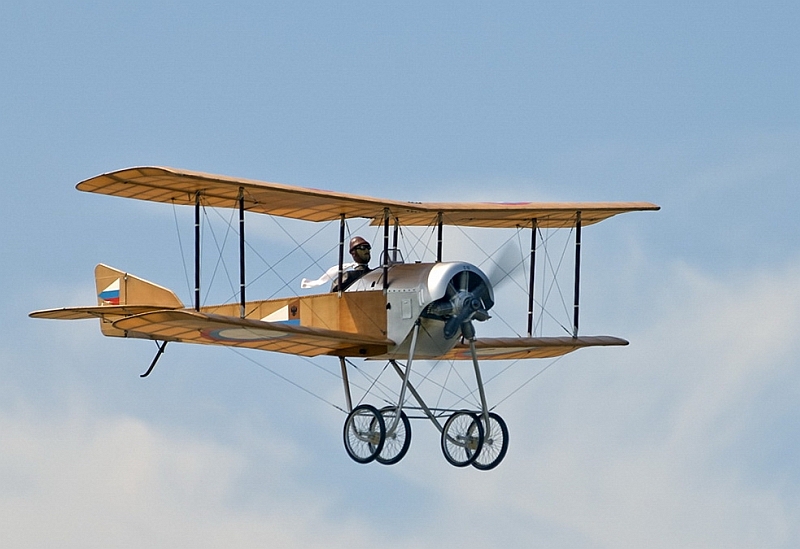
The Sikorsky S-
Although highly maneuverable, the S-
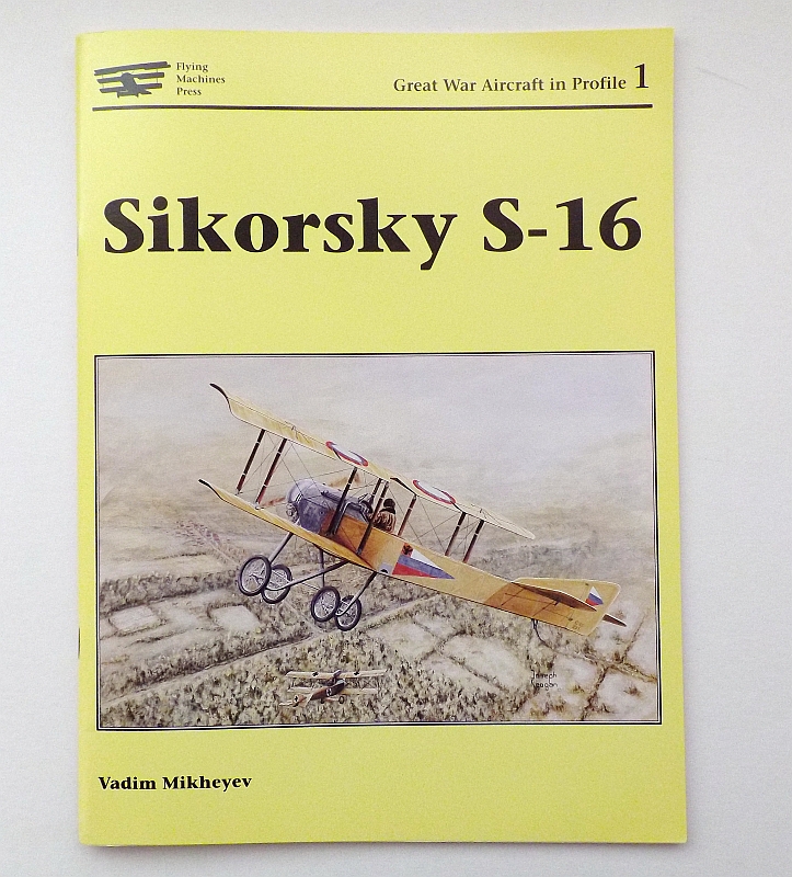
I purchased this book through the internet, it was quite a reasonable price. The books contains a very good history of this particular aeroplane with some really good black and whit archive photos. There are seven colour profile photos which give a guide to the different schemes that were used. Also within the book are 1:48 and 1:72 scale drawings/plans which is excellent for the scratch builder, there is also a two page cutaway drawing which shows exceptional details. Books like this are invaluable to the scratch builder.
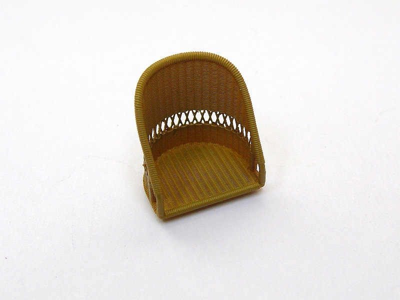
The seat I will be using in this build is one of the newly released Barracuda Studio resin wicker seats. This seat has a high back but is of the open back style, this seat matches the plans quite well for size and shape. This seat has been painted with Gunze No.71 Middlestone which gives it a very close appearance to wicker cane, I will also add seat belts to this seat.
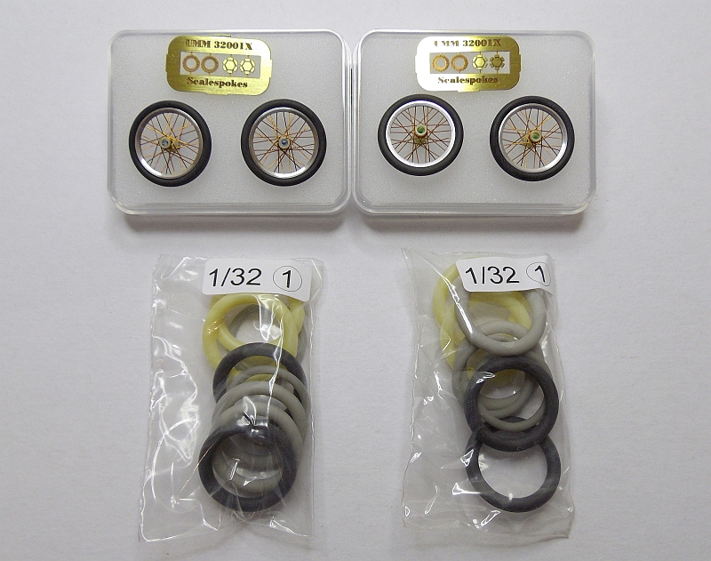
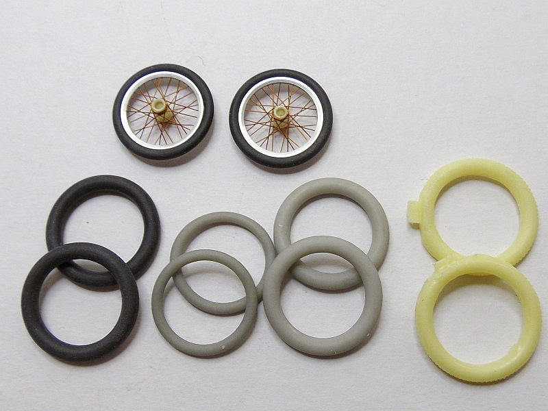
As this aircraft had four spoked wheels I purchased two sets of spoked wheels from John Vojtech at Scale Spokes in the USA. They come with a good variety of spare tyres, I will be using the thin black tyres which, when fitted to the rims gives and exact size as per the plans. These are excellent wheels and look great when painted and fitted to a model.
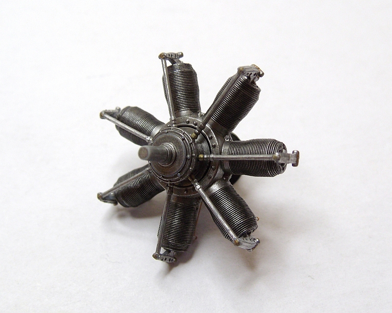
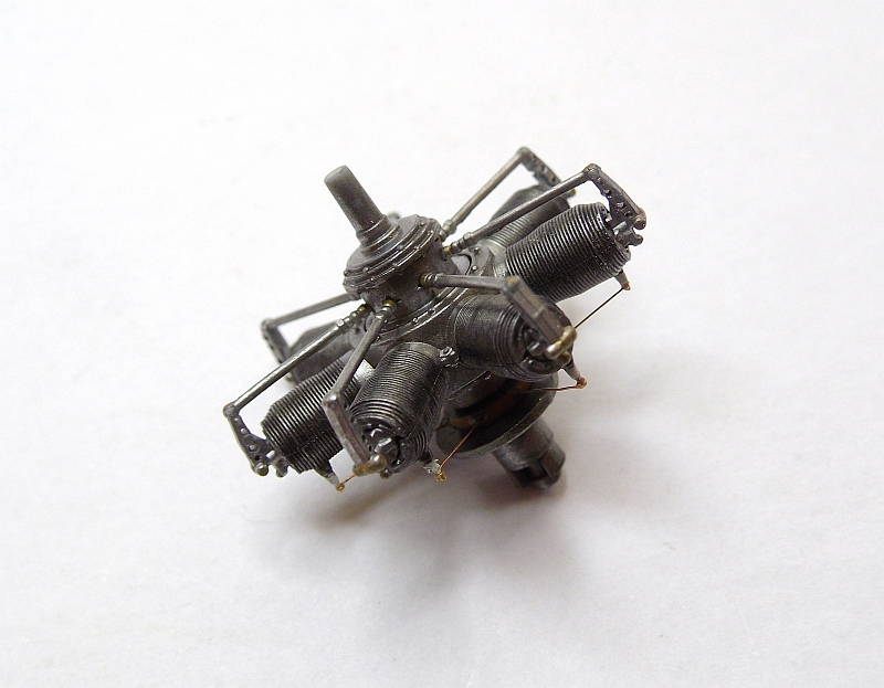
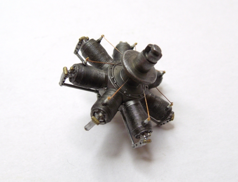
The 7 cylinder rotary engine is from one of the Wingnut engine sprues which is available from their website. It makes up to be quite a good engine with reasonably good detail especially around the head detail. I used the kit supplied push rods but as no ignition leads were supplied I used 0.13mm copper wire.
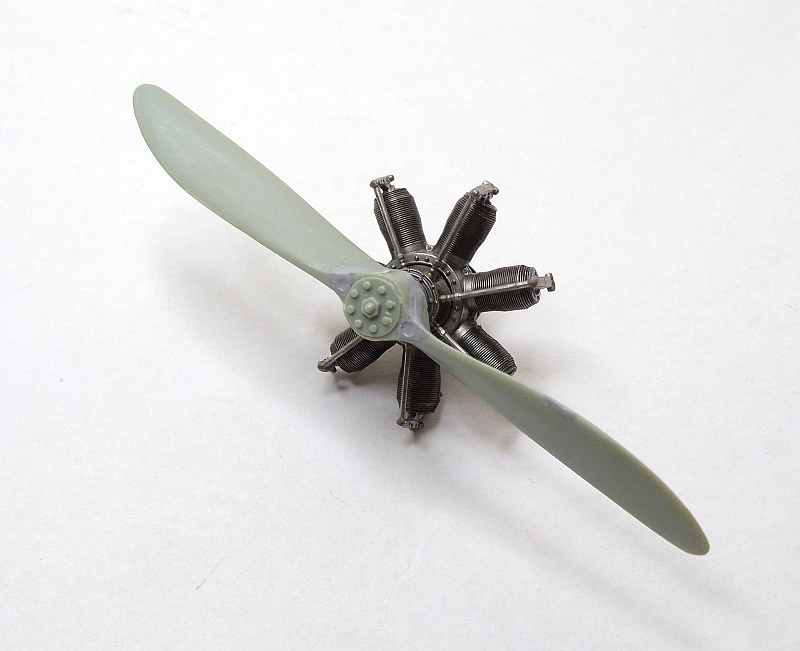
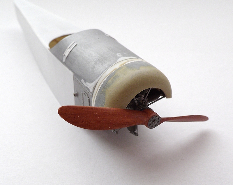
This is the propeller I will be using on this build. I have quite a good selection of spare propellers and found that this one suits the propeller profile on the plans very well, it is exactly correct for length and shape. The propeller used on the original aircraft did not show signs of the laminations but appeared to be of one colour usually of a mid to dark brown.
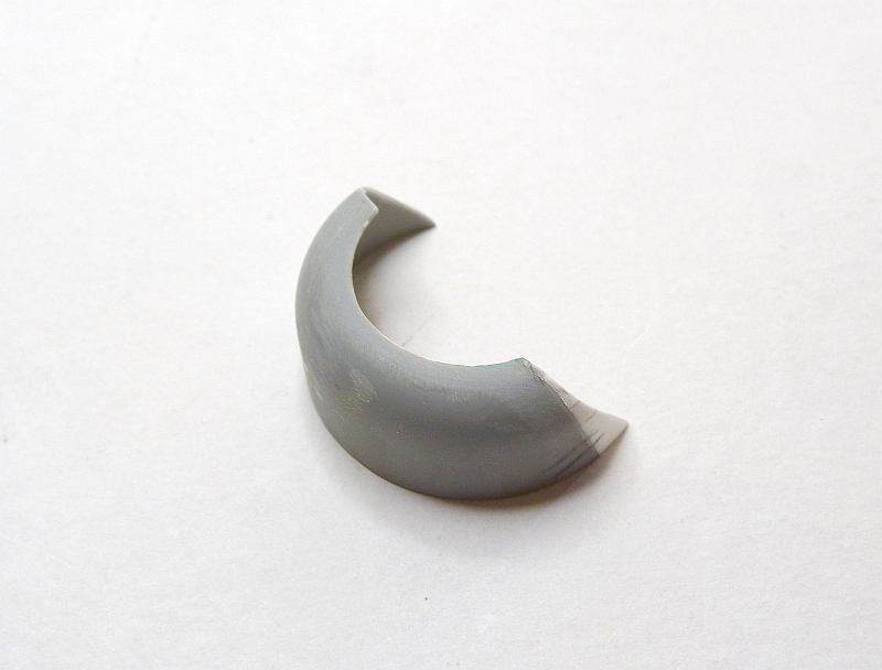
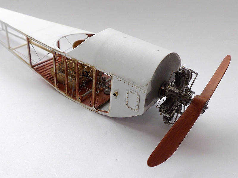
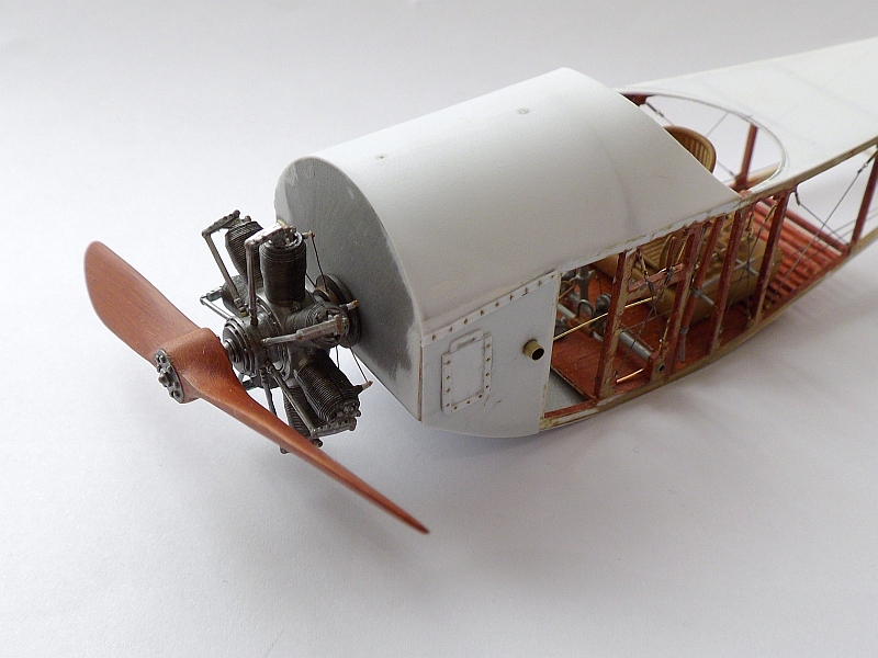
I found this spare engine cowl in my spares box so have adapted it to suit this model. It is the correct size and nearly the correct shape, I had to cut the bottom section off and shape it to suit the plans, I still need to make a few more adjustments and a bit more sanding, then I will have to add two vents either side which are visible on the main photo. There was also a guard on the side of the cowl to protect it from the machine gun flash.
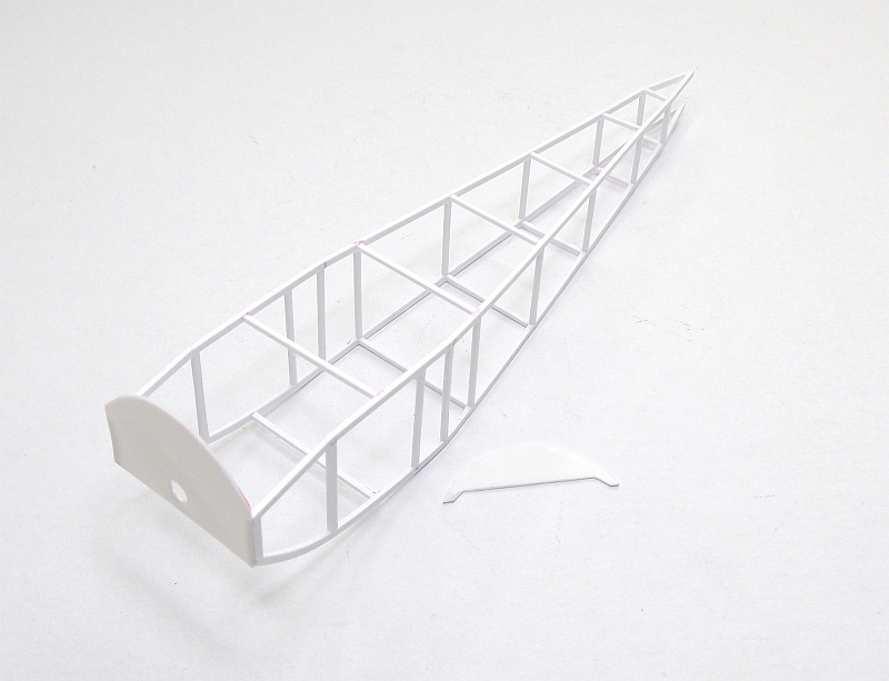
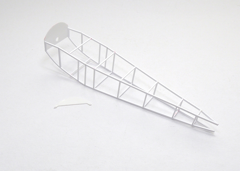
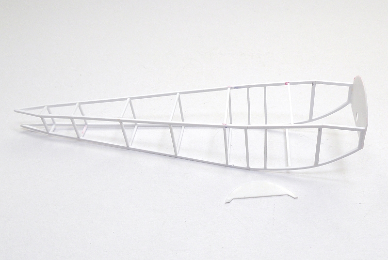
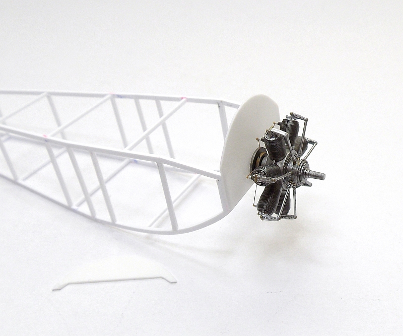
The fuselage frame is made up of 1.0mm x 1.5mm styrene strips for the longerons and 1.0mm x 1.0mm for the frames. The engine firewall is cut from 0.5mm styrene sheet as is the instrument panel. The final picture shows a trial fit of the rotary engine.
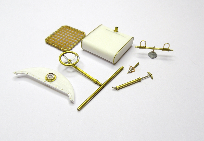
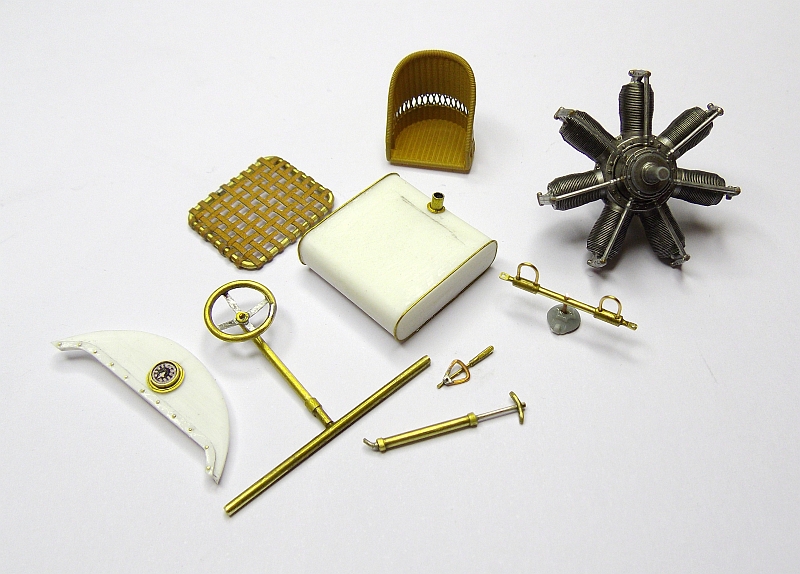
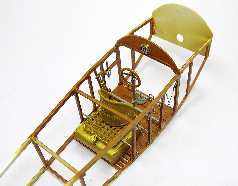
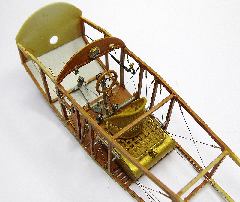
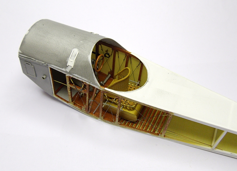
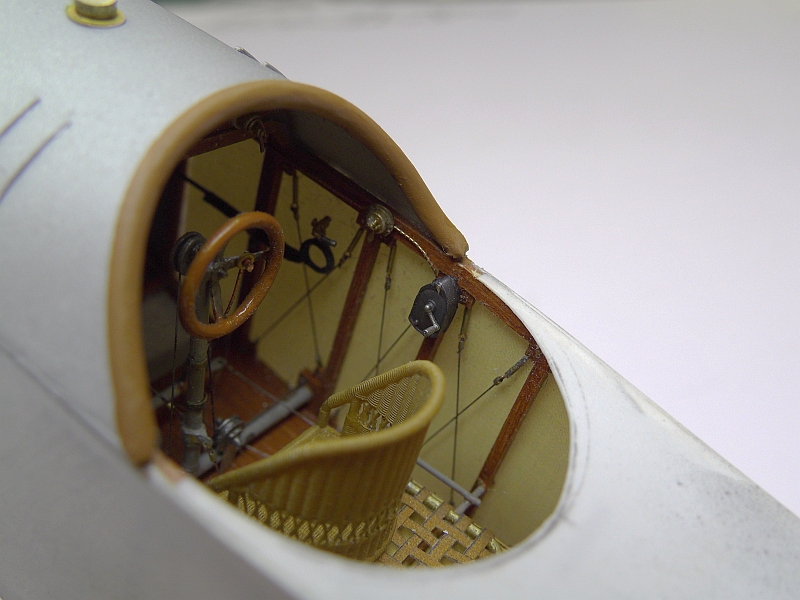
I have been making all the components for the inside of the cockpit. The fuel tank was made from two pieces of 3.0mm styrene sheet glued together then sanded to shape, a length of 0.5mm brass wire was glued long each side of the tank. I made the filler pipe from brass tube but still need to add the cap. I don’t know why but a woven frame was placed on top of the fuel tank before the seat was fixed, I made this by using 1.0mm brass wire for the frame and small strips of coloured paper for the weave fabric, I used CA to hold the paper to the frame. The control column and wheel are made from various sizes of brass tube as is the hand operated pressure pump. I made the throttle quadrant from flattened 0.5mm copper wire with small brass tube for the lever. The rudder bar is also made from various brass tubes with the foot straps made from 0.4mm brass wire. The instrument panel is 0.5mm styrene sheet cut to shape, only one instrument is shown on my plans so that is all I fitted, the instrument is made from brass tube and a bezel. The second photo shows all the components along with the engine and the magnificent wicker seat from Barracuda Studios.
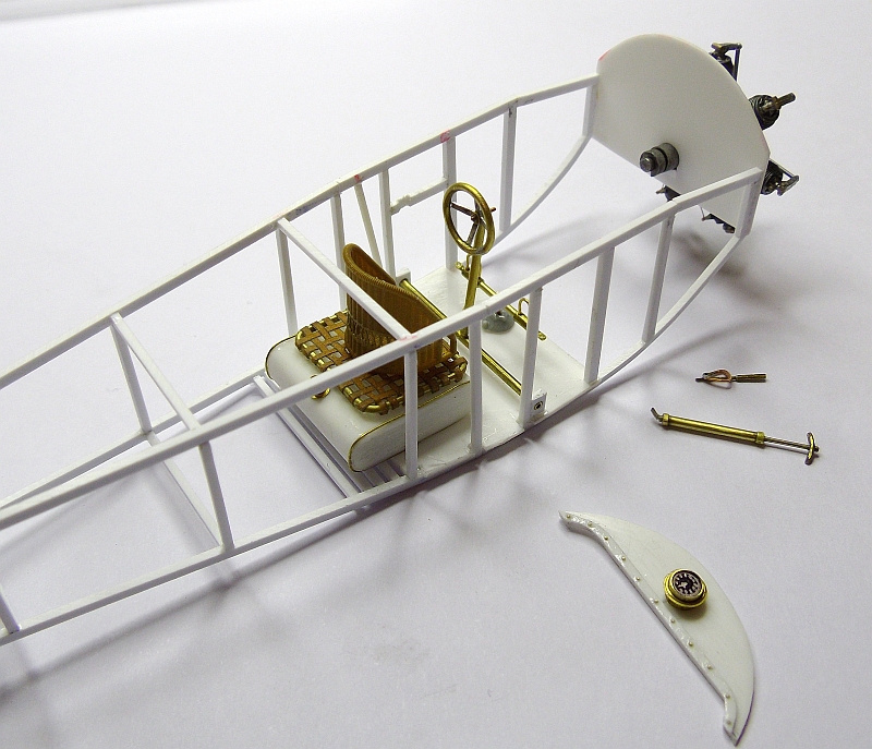
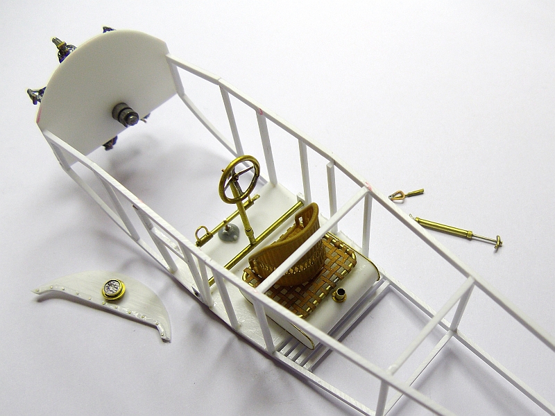
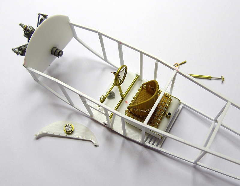
These picture just show what the major cockpit components look like sitting in there positions, the pilot seat needs to be a bit closer to the wheel to allow more of the woven section to be exposed, this was a seat for a second person.
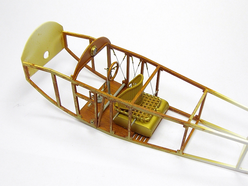
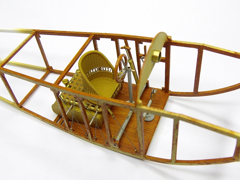
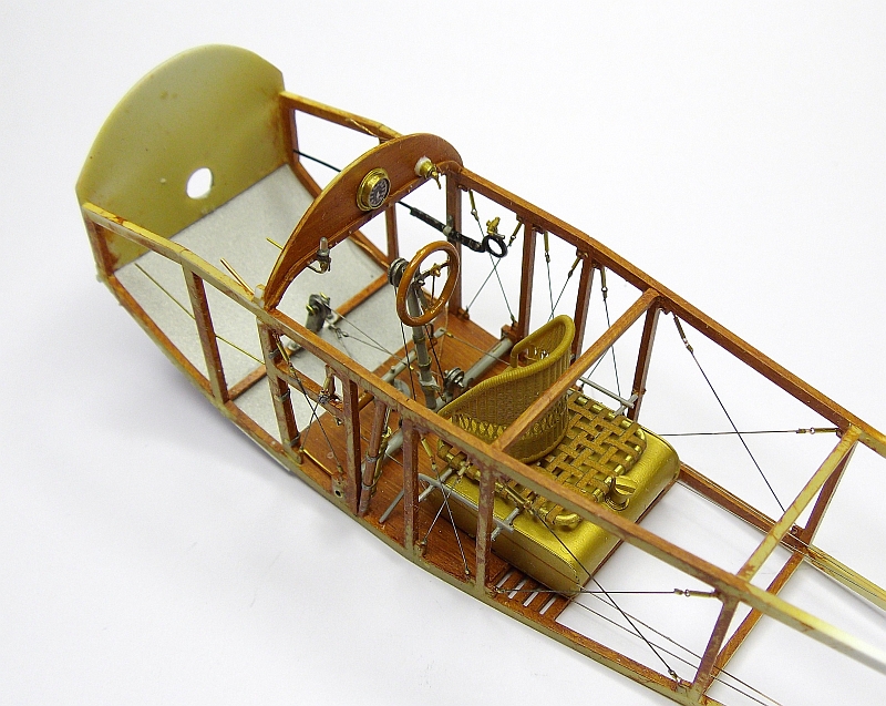
I painted the fuselage frames and floor with Gunze sail colour then added the wood using burnt sienna oil paint, 24 hours in the heat box dried the oils perfectly then I sprayed with a coat of satin clear. All the major cockpit components have now been added to the fuselage frame, I still need to add the control cables, starting magneto and switch plus a seat belt.
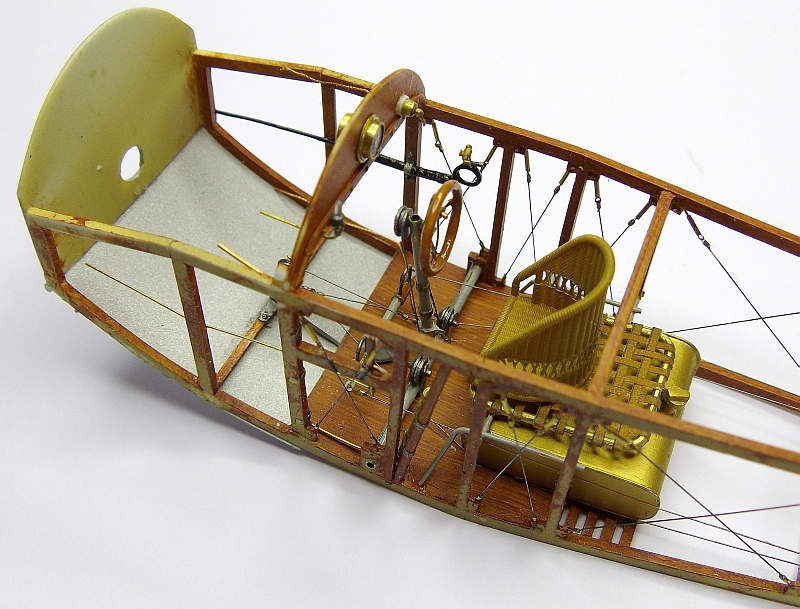
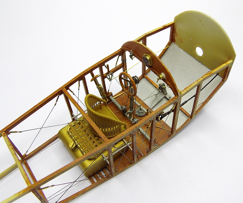
The internals are just about done, I’m awaiting the arrival of the starting magneto
and selector switch, they will be mounted on the right side and will have electrical
cables connected to them. On the instrument panel I mounted a Taurus Pulsometer,
a home made switch and the main instrument, a tacho. On the right side of the fuselage
is the fuel shut-
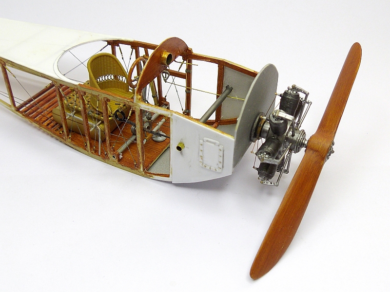
I added a length of 1.8mm brass tube to simulate the engine air intake, this tube protrudes through both sides of the fuselage. I have also made and fitted the two (one either side) engine access panels. These were small doors which lifted up to expose the rear of the engine where all the accessories are fitted.
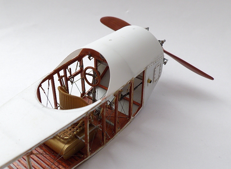
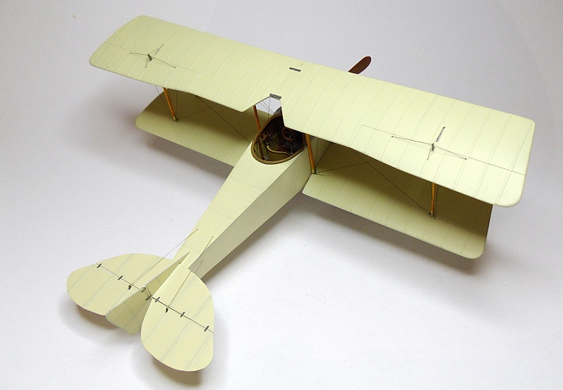
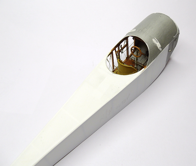
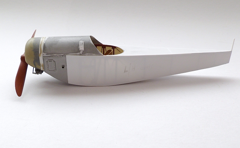
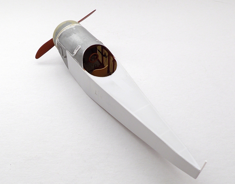
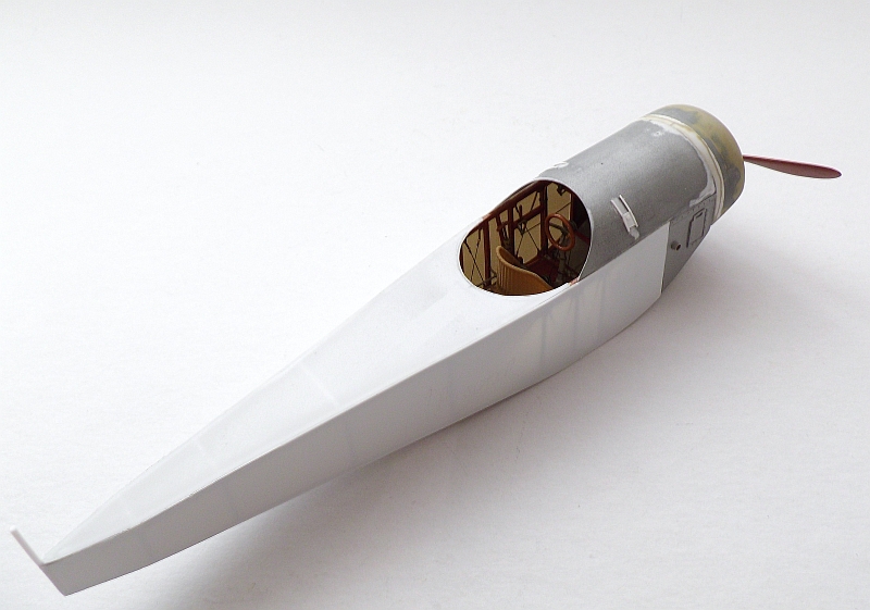
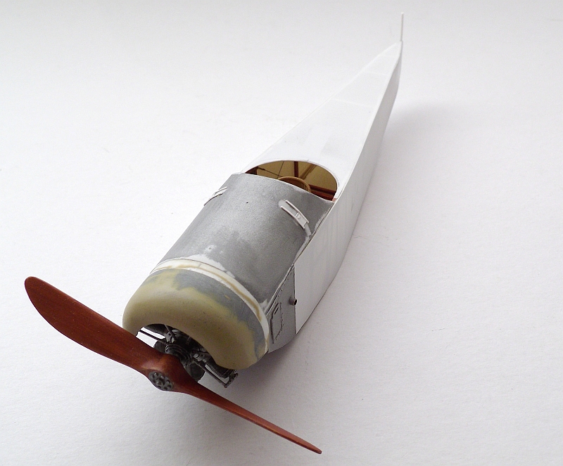
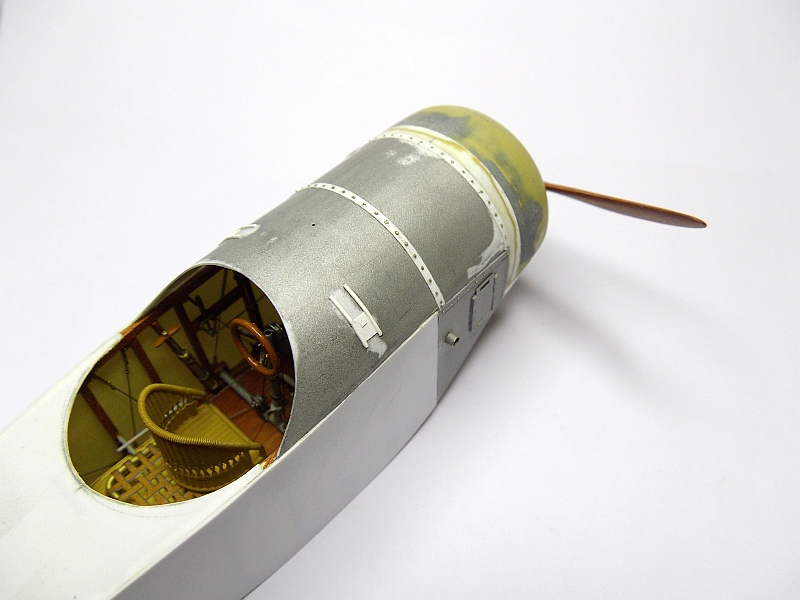
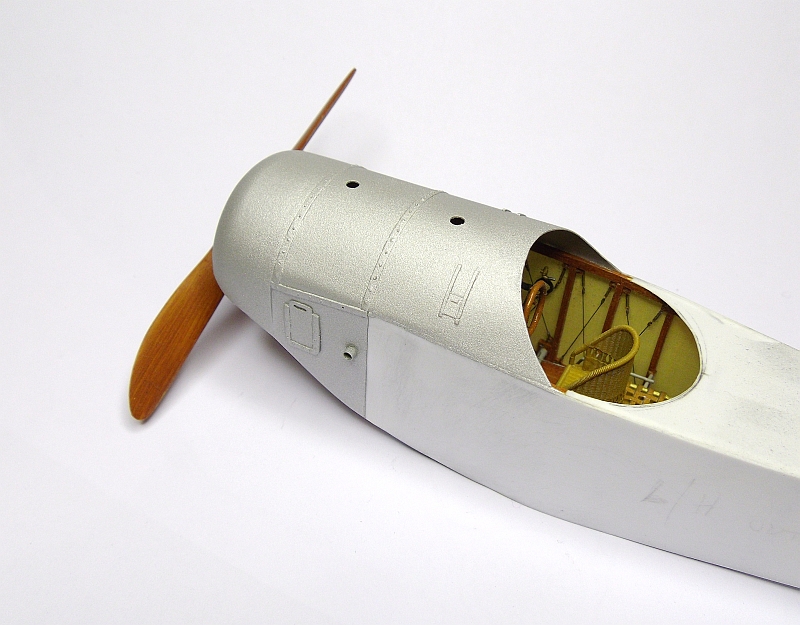
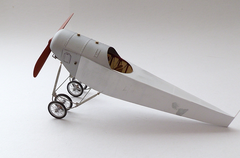
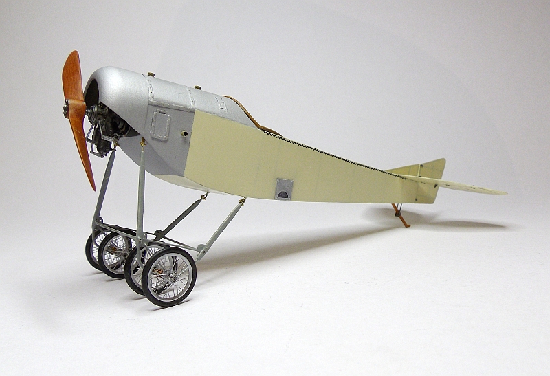
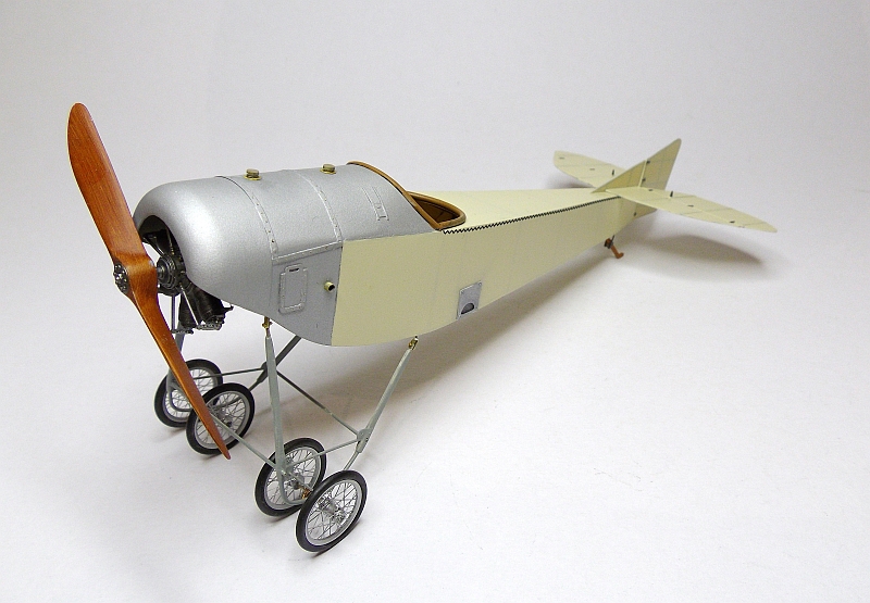
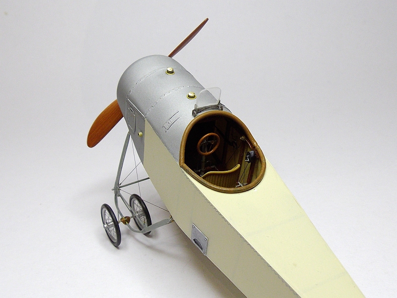
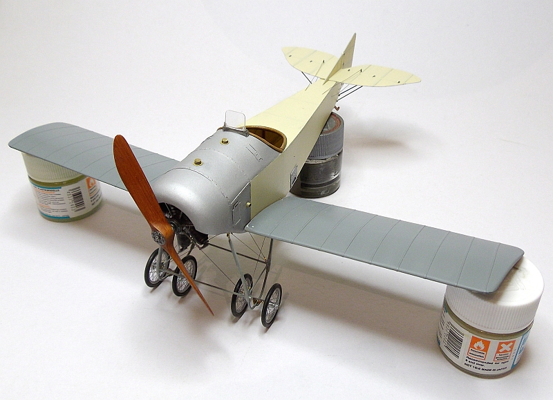
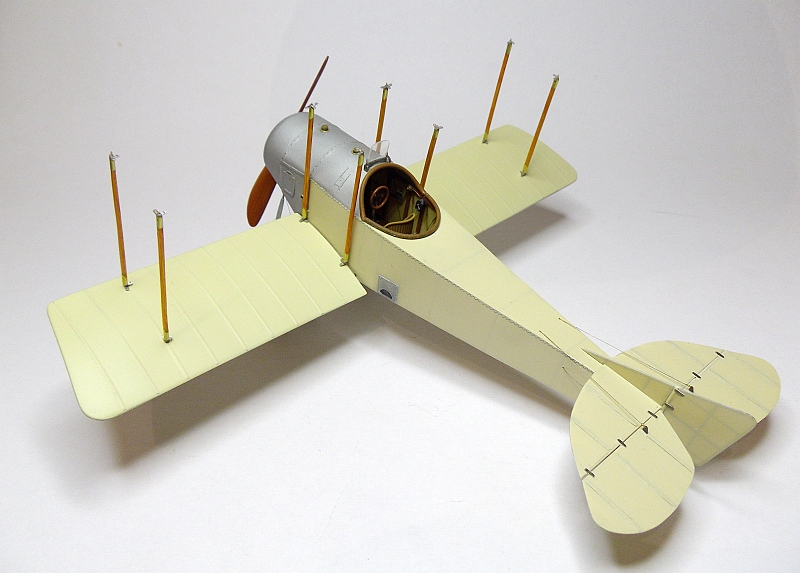
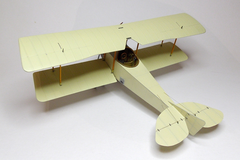
I covered the fuselage forward nose section using 0.25mm styrene sheet, this was cut to fit and the cockpit cutout was also done before it was fitted. As can be seen in the photos, the rear fuselage decking has also been fitted, this is again 0.25mm styrene sheet. The forward sections will be painted an aluminium colour whilst the remainder of the fuselage will be a CDL colour. The engine is only sitting in position for photo purposes. Note that I have cut the top fuselage covering back far enough to allow a passenger to utilize the woven seat, this was usually used for the observer but if the aircraft was used as a single seater this cover came right up to the back of the pilots seat. I also need to add the cockpit padding which will fit to both forward and aft edges of the cockpit opening, this will be painted in a leather colour.

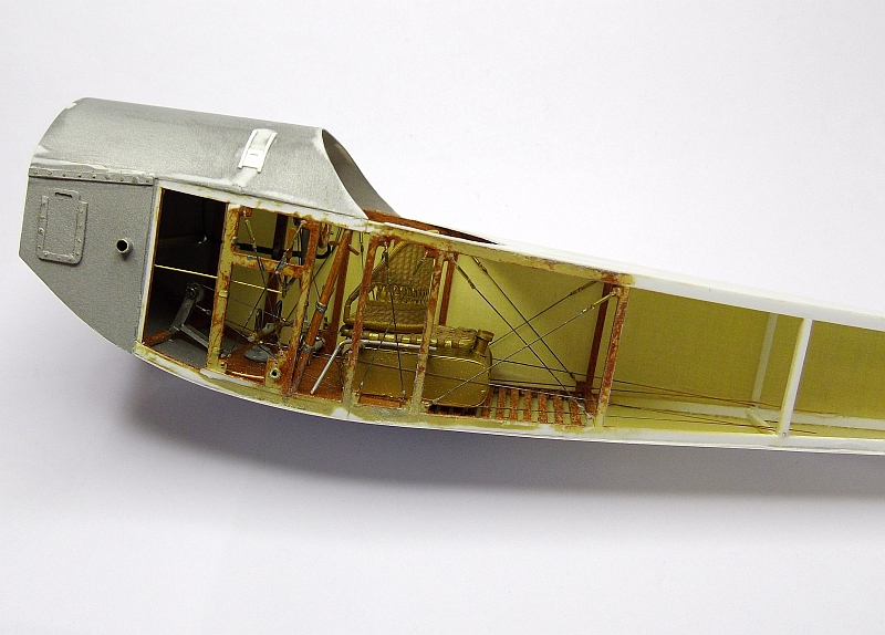
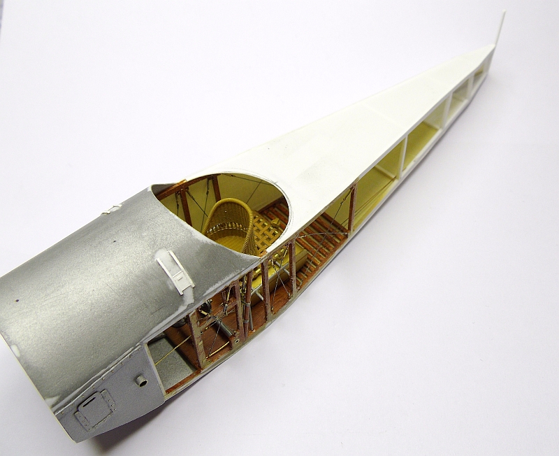
I made two more access panels, one each side of the top cowling, these were made from 0.13mm styrene sheet. The covering on the floor and the right side has now been fitted, these are made from 0.25mm styrene sheet cut to size and the inside firstly painted with Hobby Color H21 Off White. After this had dried I applied Aviattic WW1 RFC/RAF CDL decal, sheet ATT32094. As most of this inside CDL will not be visible I didn’t bother to clear coat the decal. I used Mr Mark Softer under the decal which allowed the decal to be moved into position, the decals settled down beautifully.
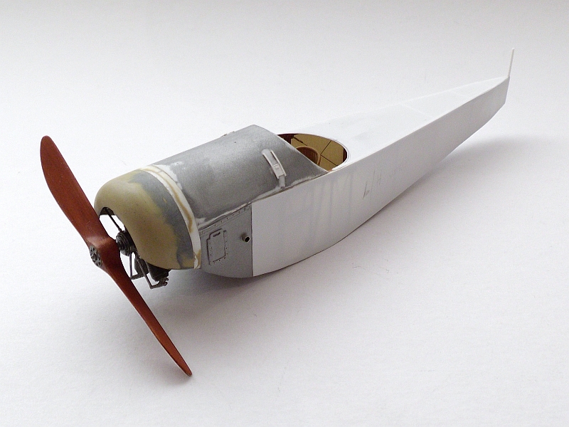
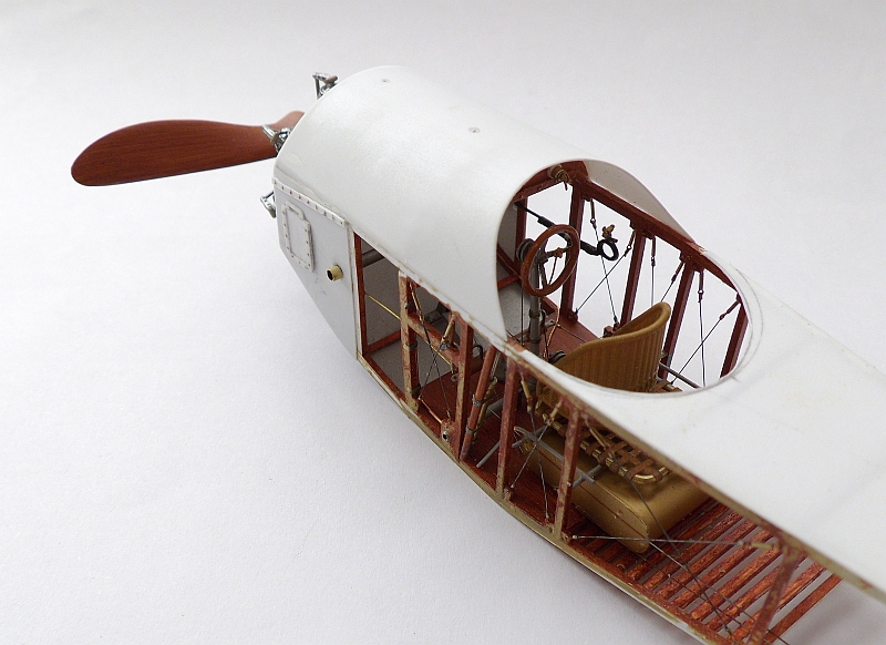
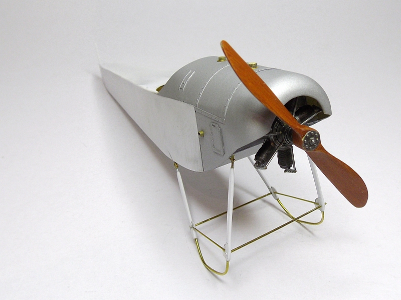
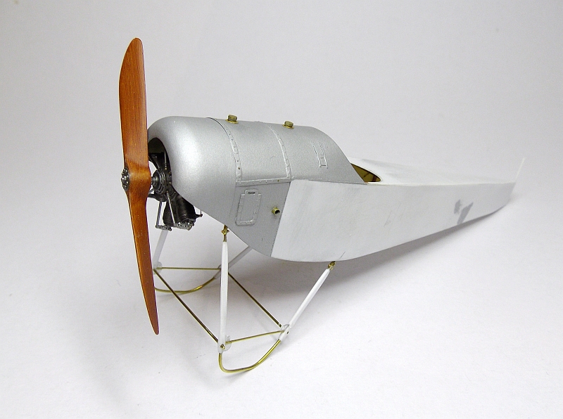
The remainder of the fuselage has now been covered, it was a very easy job to cover the fuselage frame. I have also fitted the engine, this had to be fitted before the engine cowl was glued on. I also made the two cover strip which go over the top cowling, these are made from a narrow strip of 0.12mm styrene sheet with 0.4mm holes drilled at 2.0mm intervals. Once they were glued into position I drilled the holes again and then fitted short lengths of 0.25mm brass wire into the holes using CA, once dry the excess with was trimmed off.
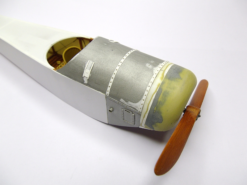

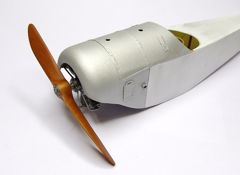
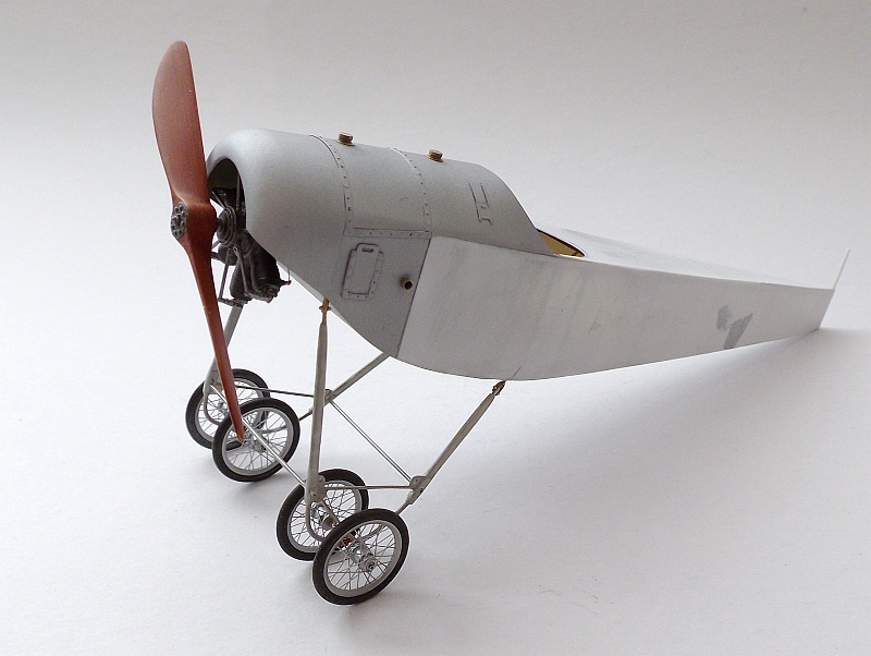
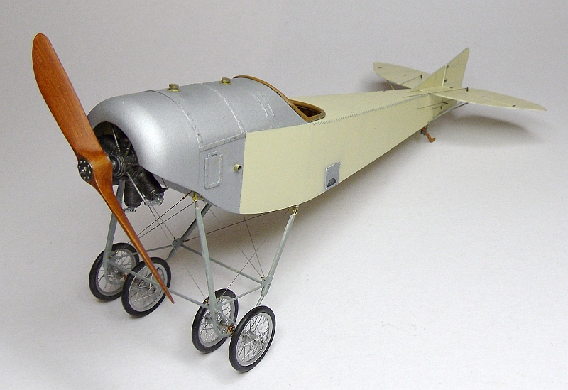
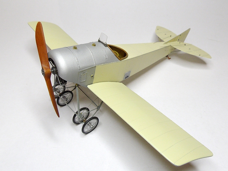
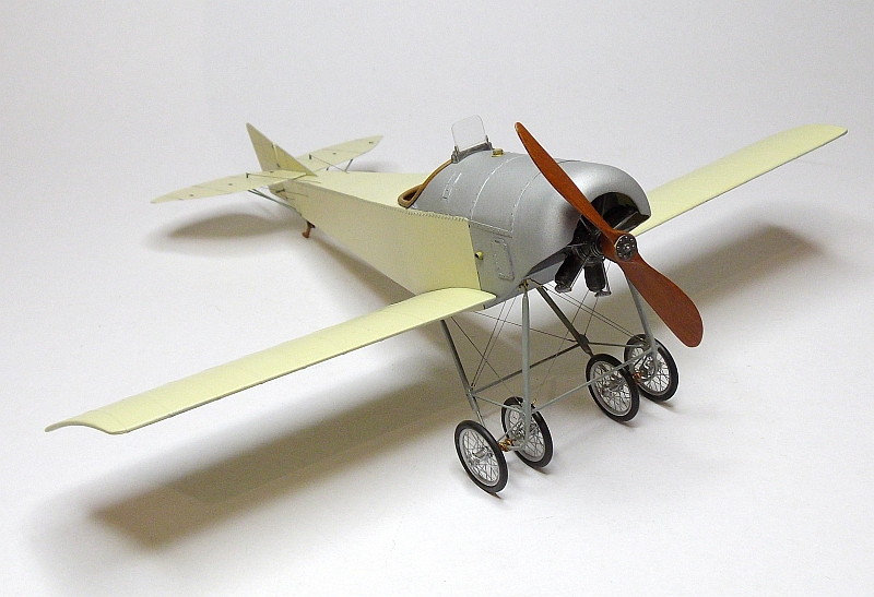
The complete nose section is now complete. I have sprayed all the aluminium pieces using Humbrol metal cote unpolished aluminium 27001, once totally dry I will give it a really light rub with 0000 grade steel wool. I also need to add the cockpit padding around the cutout edge of the forward decking. The two holes in the top deck are for the oil filler and fuel filler pipes and caps, these will be made from brass.
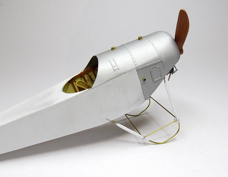

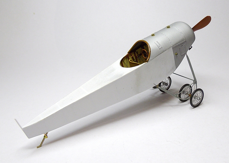
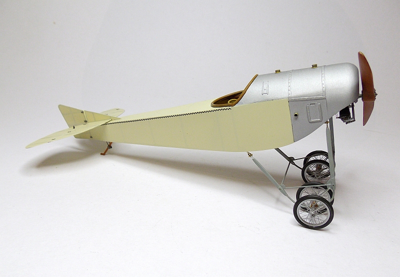
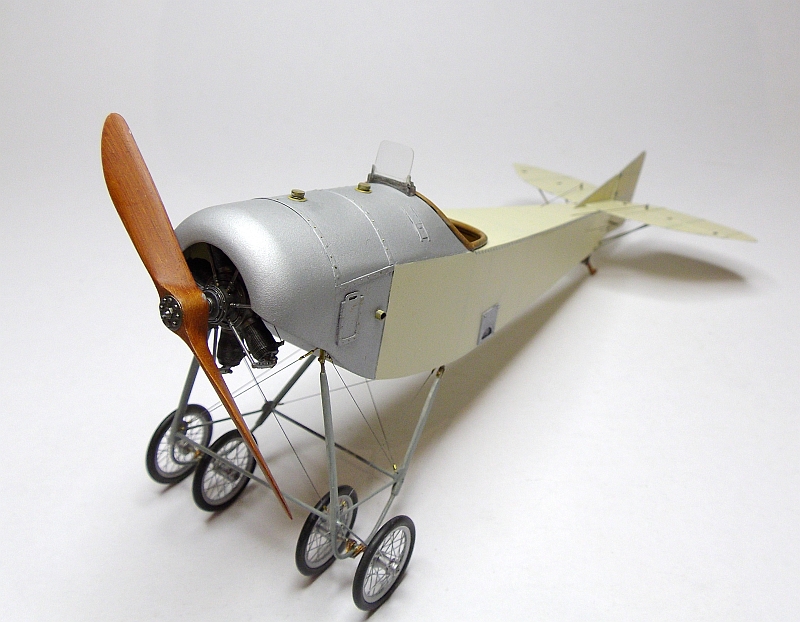
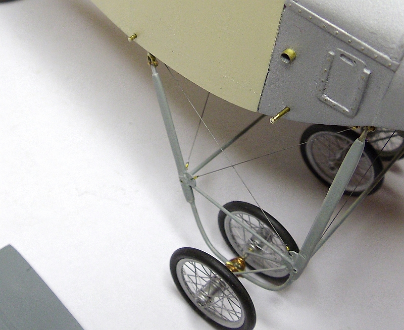
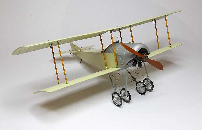
The undercarriage has now been made and fitted, it is made from styrene strips and brass tube, I also utilised some aluminium tube in the construction. Fitting the undercarriage was a simple matter of drilling four holes, inserting the undercarriage mounting pins then adding super glue, it is quite a strong assembly. The fuel and oil filler pipes and caps have also been fitted.
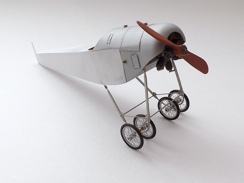
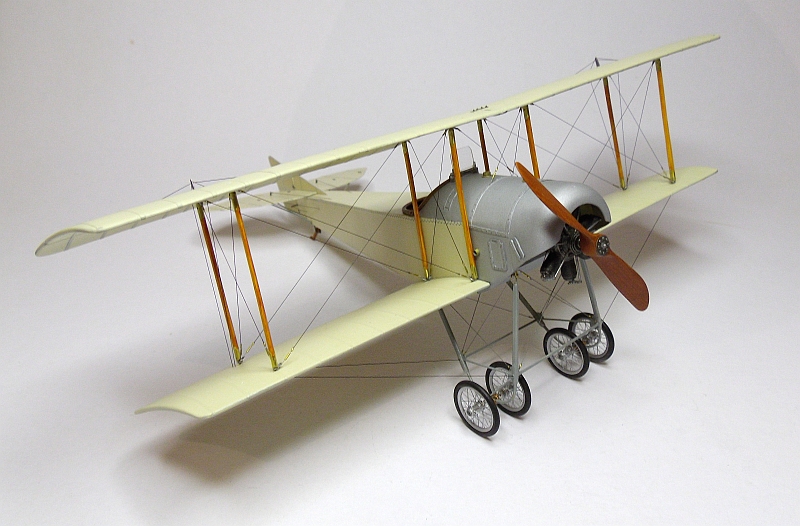
I have added the four wheels. These wheels are from John Vojtech at Scale Spokes, I painted them with Mr. Metal Color chrome silver then lightly polished them. I also fitted the “bungee” cord around the axle of each wheel assembly. The undercarriage frame has been painted using Gunze Barley Gray H334, a second coat is required. The undercarriage also requires rigging but that will come later.
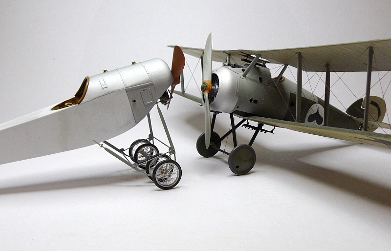
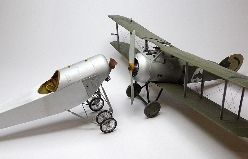
These two photos were added just to show the size comparison between the Sikorsky and the Sopwith Snipe. Both aircraft are roughly the same size but the Sikorsky stands a little taller. The third photo shows the tail skid that has now been fitted, it will be done as a wood colour.
Lukasz from Taurus Models was kind enough to send me his new starting magneto and magneto selector switch. This is an amazing set which by the way needs to be assembled and painted. I connected the two items with a short length of electrical cable. All these little aftermarket accessories adds a lot of extra detail to the model.
I made the two elevator control horns from 0.18mm thick brass sheet. They are 5.0mm long and 1.8mm wide, once they were cut to roughly the correct shape I sanded them to the size required. For the cable connections I drilled 0.4mm holes using a tungsten carbide drill bit.
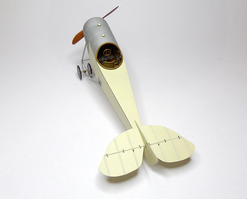
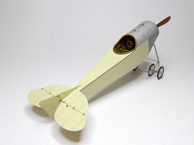
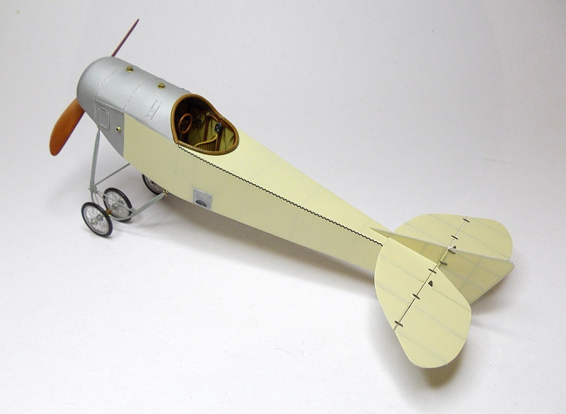
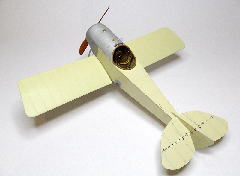
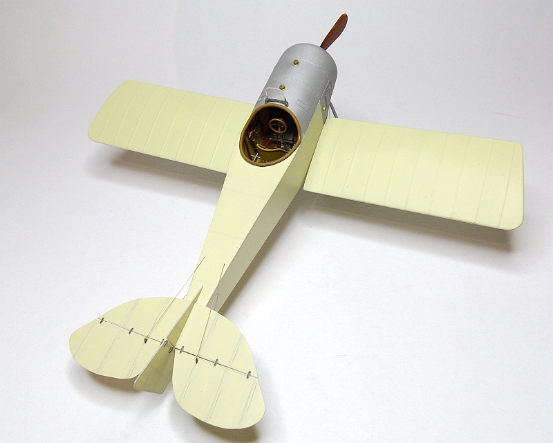
These pictures show the tail which has now been fitted to the fuselage. The tail was made from 0.5mm styrene sheet cut to shape then sanded, ribs were added using 0.25mm styrene strips glued to the tail plane then sanded. The small hinges are made from 0.12mm styrene sheet cut and sanded to shape then glued to the surface, I then drilled 0.3mm holes in each end of each hinge and inserted a small length of copper wire, these were held in place with CA. The stitching along the side of the fuselage are Archer Resin Decals, these are easy to apply, just like normal decals, I still need to give them a wash with the fuselage colour paint to tone down the harsh black look. Next stage will be the tail rigging, I have already added the elevator control horns.

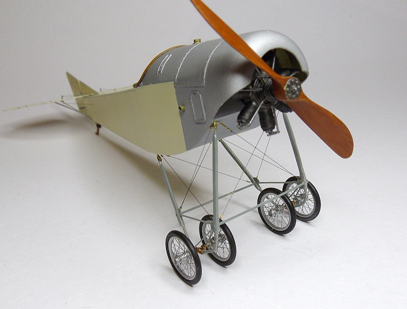
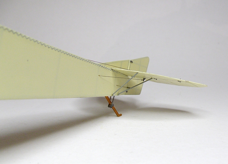
I have fitted all the undercarriage rigging. I used ModelKasten 0.13mm elastic rigging thread, this can be tensioned without putting undue pressure on the undercarriage. I used 0.5mm brass tube for the small rigging connectors and super glue holds it all together really well. I also added all the control rigging to the tail, I used 0.12mm monofilament for this process but used the same brass tubes and super glue. All the rigging lines on the undercarriage and the control lines on the tail have been painted with Mr Metal Color Stainless, I did not buff these lines. I fitted the four tail plane metal stays which fit under the tail surface, for these I used 0.6mm brass tube cut to the correct length. The stitching along the side of the fuselage has been given a coat of the fuselage colour to tone it down a bit, it stood out too much when a full black.
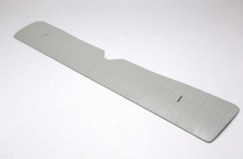
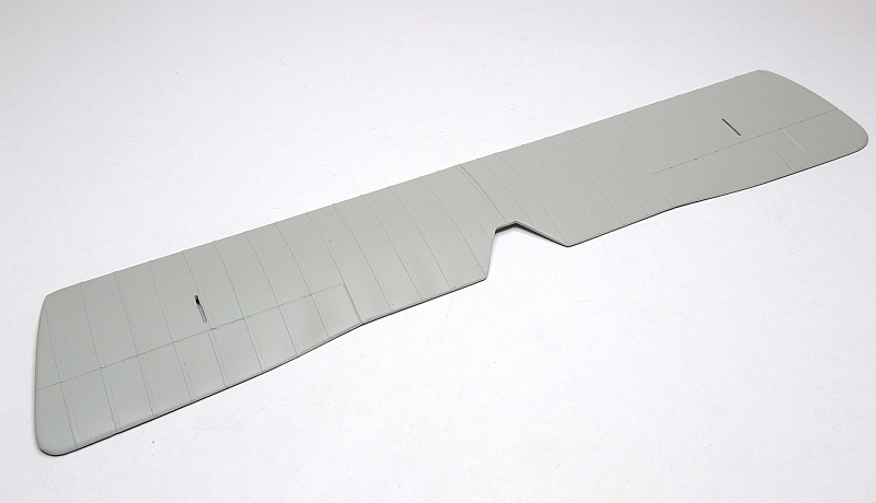
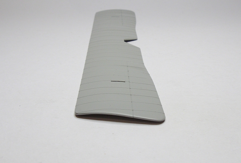
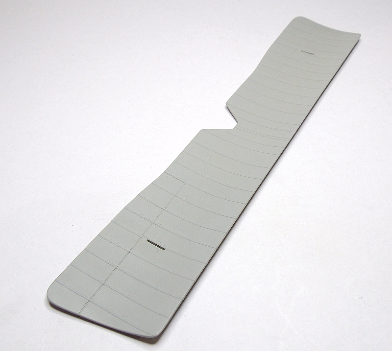
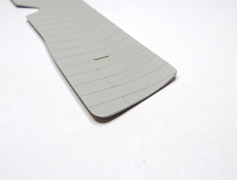
The top wing is made up of three layers of 0.40mm styrene sheet cut to size and shape then glued together. While the glue is wet I wrapped the wing around a 100mm PVC pipe and using duct tape held it at the correct curve. I left the tape on overnight and when removed it retained the shape I required. The photos show the curve that was achieved by using this method. Slots where cut in the wing to accommodate the aileron controls and wires. The rib tapes were applied by using 1.0mm wide Bob’s Strippers, these adhere well and once all in place I sprayed the wing with some automotive primer. These pictures show the wing straight after spraying, I now need to give the entire wing a sanding then a coat of the correct colour.
I fitted a small windscreen to the top of the fuselage. I found the windscreen in my spares box but need to cut the clear glass out and replace it with a slightly higher piece. To fit this to the fuselage I drill two 0.3mm holes into each corner of the frame, I then super glued two length of 0.24mm brass wire into the holes. Two corresponding holes were drilled into the fuselage and the windscreen fitted, a small drop of CA was applied to the wire were it protruded inside the cockpit, the excess wire was snipped off.
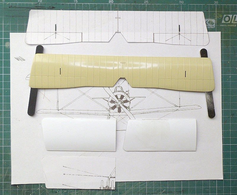
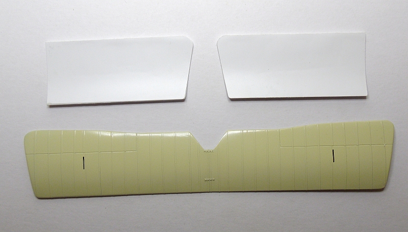
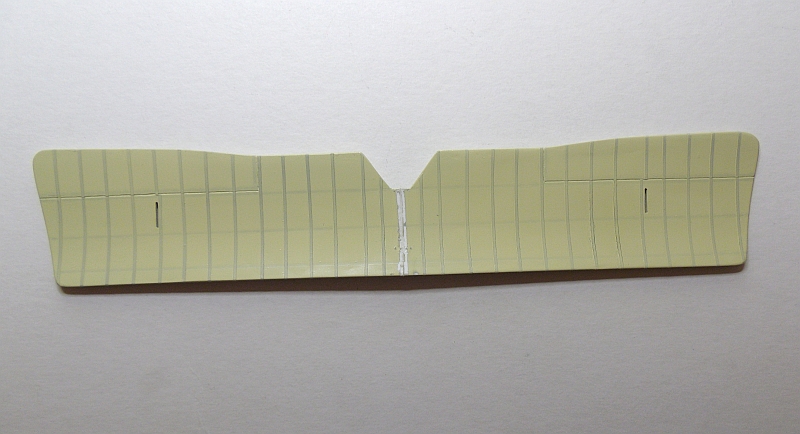
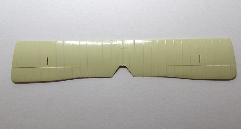
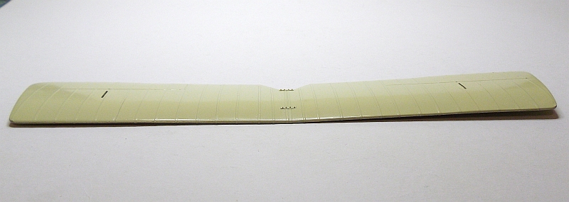
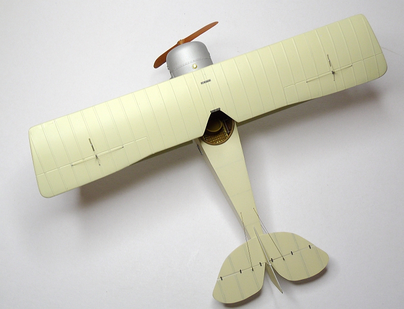
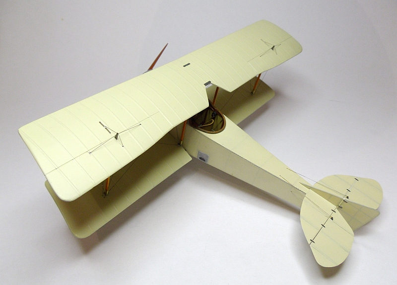
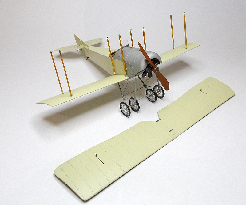
These pictures show the top wing nearly completed, I have set the dihedral and given the wing a coat of the final colour, still need to add a few coats of clear. The two bottom wings have now been formed and require sanding then the ribs applied. The first photo shows the plans I followed, these came from the book I purchased then I scaled them in my drawing program. The centre section under the top wing will be covered with a wing joining strip then repainted. As this model will depict an unarmed trainer there will not be any markings on the wings or fuselage.
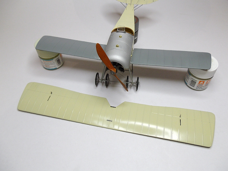
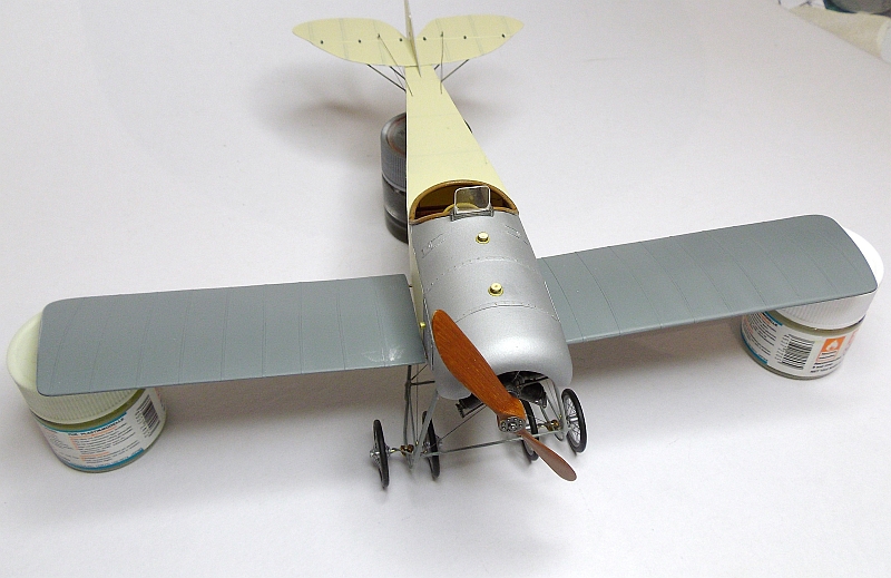
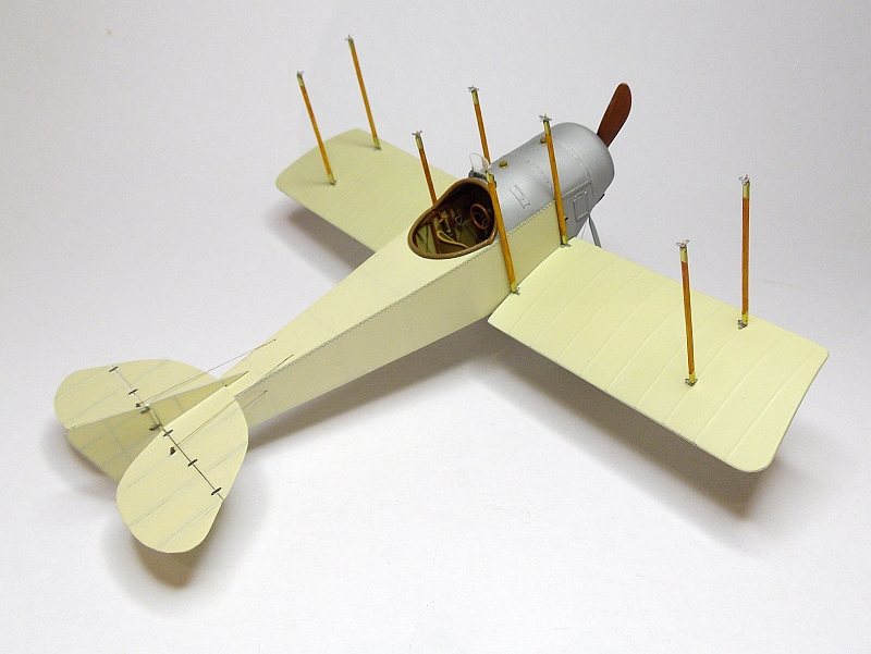
I fitted lengths of 0.8mm brass tube through the fuselage to act as bottom wing supports. I drilled 0.8mm hole, two in each wing root, to accommodate the mounting brass tubes. Once the tubes were super glued in place I slipped each wing on the tubes, the paint bottles at the wingtips gives me the correct dihedral. As the fuselage tapers the trailing edge of the wings do not touch the fuselage side so will be held in place solely by the brass locating pins. Nest job is to paint the bottom wings then fit them permanently. I made two aileron control horns from brass sheet. I cut two slots in the ailerons then slipped the control horns in place, these where then super glued in place. Once the bottom wings are fixed in place I will then make the struts, a total of eight, these will be made from bamboo tooth picks which I find are very easy to work and are very strong.
The bottom wings have now been painted and are fitted to the fuselage. I used 5 minute epoxy in the locating holes in the end of the wings and also on the four brass tubes protruding out the sides of the fuselage, I also ran a very small amount along the wing root where it touches the fuselage. The wings were supported while the glue dried to give me the desired dihedral. Once the epoxy was dry I applied super glue to the top and bottom of the wing root where it touched the fuselage side. I left the whole plane for about four hors before removing the supports under the wings, once the supports were removed the wings retained their dihedral. Next stage of construction is the making of the struts.
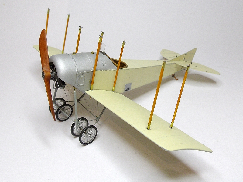
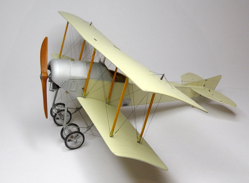
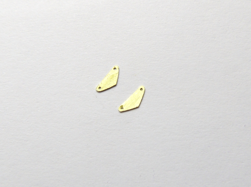
The wing struts are made from bamboo tooth picks. The tooth picks start off by being 2.0mm round so I flatten two sides so they end up being 2.0mm x 1.0mm, being bamboo they are very strong. I used 1.8mm brass tube half flattened then filed to shape and fitted to the top and bottom of each strut. I drilled a 0.5mm hole in the both ends of each strut then fitted a length of 0.4mm copper wire, CA holds it well. I drilled 0.5mm holes in the wings to locate the struts, a small drop of CA holds them in place making sure they are aligned correctly. I painted the struts with Humbrol clear orange. The small rigging brackets which are fitted to the top and bottom of each strut are made from thin aluminium sheet (coke can) cut and filed to shape.
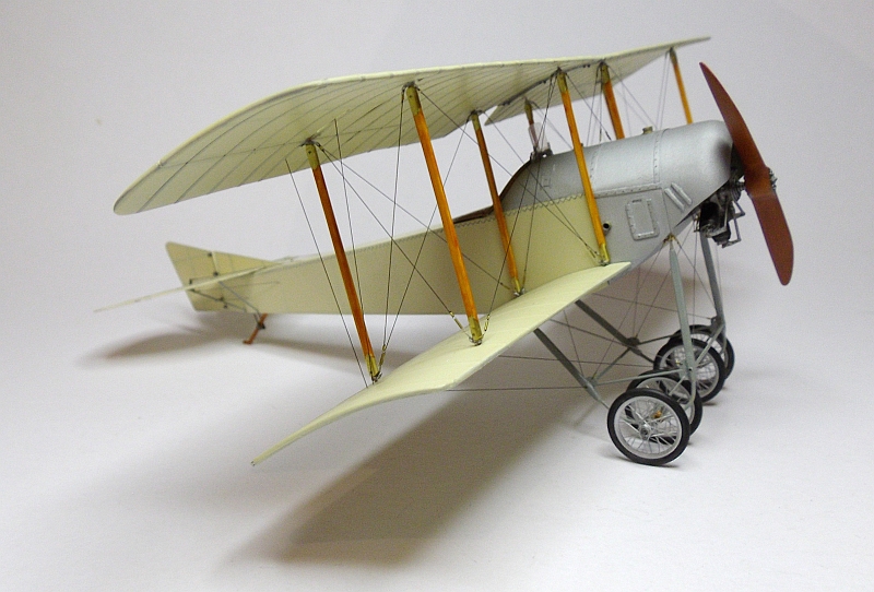
The top wing is now fitted but not first without a few issues. The plans I have did not show under the top wing so to find the correct location positions was a little difficult, it was a matter of trial and error with the top wing having to be removed twice and the locating holes moved. Even now it is still not perfect but I’m afraid if I remove the wing once more damage will occur. The wing assembly is quite strong without the rigging so I will be using the elastic rigging line, not a great deal of rigging tension will be needed. The top wing mounting was secured using CA, this gives a very good bond. The dihedral built into the top wing has retained its shape perfectly and will not require excessive tension on the rigging line.
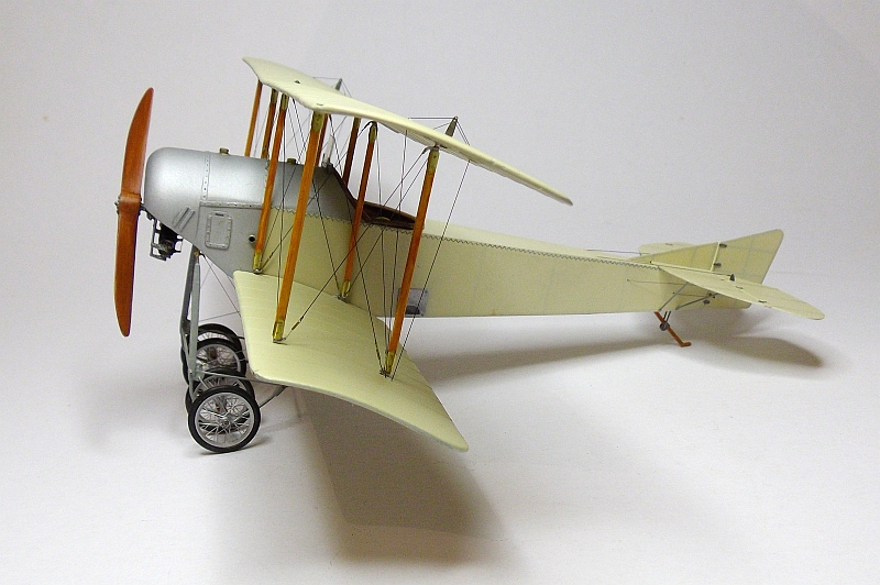
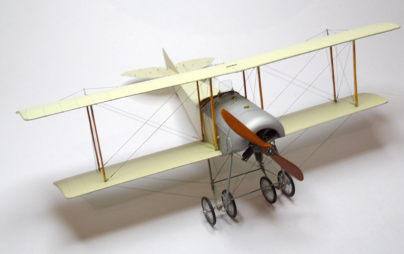
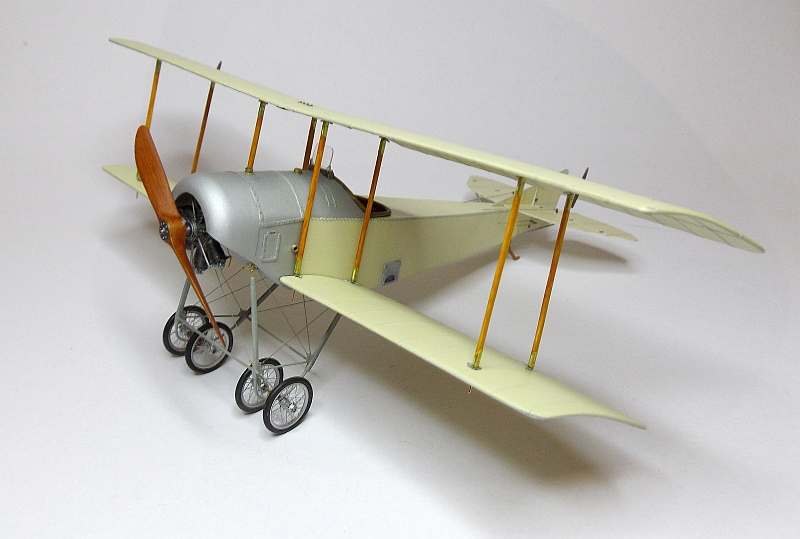
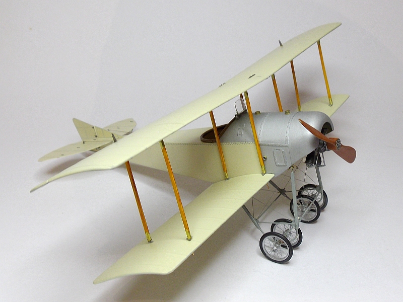
This model is now completed, I used 0.13mm ModelKasten elastic thread for the rigging, a little expensive but an excellent product. Although a very basic aeroplane it was still a joy to scratch build.