


Most of the cockpit area has been completed, I still need to add seat belts and a bit of weathering. I made the instruments from brass tube and fitted them in place of the kit items. The timber look was created using gunze water paint as a base then wood grained with artists oils. The whole interior was clear coated using Humbrol Matt Cote. I used the kit supplied instrument faces which are very good. The engine is only dry fitted just to see how it looks and to check the fit. The kit has gone together very well to this stage with no problems being encountered.


I have started the painting, the fuselage is almost done as is the upper surface
of the lower wing. I’m doing this one as 134/17 Flieger Abteilung @ 263 hence the
two tone green on the fuselage. The rudder is painted gloss white ready for the decals,
then it will get two coats of matt clear. I painted the fuselage using Humbrol enamels
thinned to 50 -


The bottom wing went on very well, the only concern is the alignment of the small struts with the fuselage, when fitting the wing keep an eye on the strut location in comparison to the fuselage.


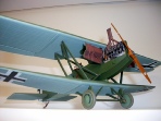
All the fuselage decals are now on the the fuselage has been clear coated using Humbrol Matt Cote. This is a brilliant product which, when thinned with enamel thinners sprays beautifully leaving a semi satin smooth even finish. The engine is fitted but the guns are just sitting in position for photo purposes. The undercarriage fitted very well is quite a sturdy assembly. The axle could be replaced using brass as once completed it will be a weighty model, time will tell if my kit plastic axles hold up to the weight. Overall progress so far has been without any major issues.

The kit is supplied with a built in error, there is a 3mm gap at the inboard end
of the ailerons on each side of the top wing. To rectify this I extended the outer
wing attachment panels by using thin plastic strips glued in place then sanded smooth
to match the existing panels. This is probably not correct but it was an easy fix
and matches the bottom wing. Throughout the entire build of this kit this was the
only error I encountered, not what you would call a major issue but one that should
not have got through the system un-

These are the engine cowls which I will be leaving in the open position so I added a bit more detail to the inside of the cowls. I added the internal bracing and drilled holes in the strengthening frame work. I removed the plastic hinges and replaced them with metal ones, I need more strength here to support the open cowls. Shading is done with graphite powder then clear coated with Matt Cote.

This picture show a dry fit of the top wing using only four of the eight struts. Control cables are also fitted to the rudder and elevators. Top wing is complete apart from the radiator and a coat of Matt Cote to the under surface. Decals went on very well.
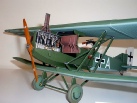
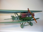
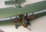
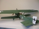
Here are some photos of the completed model. It was a real joy building this kit, the detail is very good but any amount of added detail would only enhance an already brilliant kit. It ends up being a big model but does not look out of place amongst other 1:32 scale WW1 aircraft models. This is a kit that could quite easily be tackled by someone who has never built a WW1 aircraft before, the lack of rigging is certainly a plus for would be first timers. The corrugated wing surface makes decal application a little tricky but with care and a little experience there should be no problems. In the eyes of many it is an ugly looking aeroplane and I suppose if you compare it to the Albatros D.III or the Pfalz D.III they are probably right, but the Junkers J.1 still has it’s place in history and deserves to be recognised for the contribution it made. I like to keep my aircraft as straight from the factory finish so I don’t apply weathering.
Paint colours used
Fuselage and wing -
Dark green -
Exhaust stack -
Underside of wings -
Magneto caps -
Stitching -
Timber -
Fuselage and wing rivet highlighting -
Tyres -
Finish coat -
Before applying decals I sprayed Humbrol No. 35 Full Gloss Clear.
Decal application -
I made good use of my heat box to help dry the paints and to keep the dust off while things were drying. My heat box operates at approx 50 degrees Celsius.
—-


I have been asked by many people to add a description on how I detailed the engine, I did not keep a photographic record so I have scanned photos and drawn a picture, hopefully this will give you a clearer picture of what I did. Please excuse the poor quality of the scanned photos.


Use the two cylinder halves that do not have the push rods attached. Drill 0.5mm
holes into the crankcase where the push rods are going, drill right through into
the crankcase cavity, it will make fitting the push rods a lot easier. As per the
diagram, trim away the moulded plastic rocker are support right back to the simulated
valve springs. Once it has been cleaned up and using a piece of 0.13mm (or similar
size) soft copper wire, wrap it around the moulded springs, I did 6 coils leaving
a small gap between each coil. Secure the wire with a small drop of CA at the top
and bottom, trim off any excess wire, continue until all 24 valve springs are completed.
Drill four 0.4mm holes under the rocker arm assembly to take the 0.4mm brass tube
which acts as the rocker support. Drill four 0.4mm holes in the top of the cylinder
to correspond with the rocker supports in the rocker assembly. Insert the brass tube
into the cylinder but have them longer than what is required, trial fit the rocker
assembly and keep trimming the brass tube until a neat fit is obtained. Before securing
the rocker assembly drill a blind 0.5mm hole where the top of the push rod will fit
into the rocker. Cut 12 lengths of 0.5mm brass tube to act as push rods, insert them
into the crankcase through the pre-
I made the plug lead conduit from plastic card, this is cut to shape and at the appropriate
locations a 0.3mm hole was drilled to take the plug leads. I secured the conduit
to the engine by drilling two 0.4mm holes through the conduit and into the cylinders,
I then inserted a short length of 0.4mm brass tube and fixed it with CA, make sure
that the conduit is parallel with the engine, do this on both sides of the engine.
All the plumbing is straight forward by using different size copper wire bent to
the appropriate shape and fitted into the correct size pre-
correctly, secure with CA. The two photos of my completed engine show the sizes of the copper wire I used, but the choice of wire sizes is entirely up to you, I used what I have on hand. The small PE pieces wrapped around the intake manifolds are from left over PE frets, very useful to keep this material as there are many uses for it, it is held to the manifold by a small drop of CA on the inside where the bent pieces meet (unseen).
I hope this description helps in some way, as I said earlier, I built this model before I started my web site so a full photographic record was not necessary. If you have any questions about detailing this engine please feel free to contact me, I will endeavour to answer any questions you may have.
Many thanks to all those who contacted me and requested this engine detailing description, my web site is here to help and over time I will be adding much more in the way of modelling techniques.
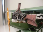
This is the Benz BZ4 engine for the Junkers. I added valve springs, rocker arm supports, push rods, additional plumbing, throttle linkages, plug leads, plug lead conduit. I used coiled small diameter copper wire for the valve springs and CA to hold them in place. The extra plumbing is made up from different size copper and brass wire. I added the extra detail because I will be displaying this model with the engine cowls open. The exhaust is painted using Humbrol rust then weathered using graphite powder, I then sprayed it with a coat of Humbrol Matt Cote. The colours for the engine are as per the kit instructions.