
I wrapped fine copper wire around the top of the control column to simulate the binding. I replaced the column shaft with a 0.8mm metal shaft, a 0.5mm brass tube was fixed to the bottom of the column for a cable guide. The rudder bar and column support are painted a dark wood colour, cockpit floor is aluminium up front and CDL aft of the control column. Fuselage framing is light wood done in oils over water paint. Instrument panel has been base coated with acrylics waiting for oil paint wood graining. All metal brackets will be painted black.

Fuselage frame has been clear orange coated and then clear coated. I have started fitting the turnbuckles to the frame, 6 on each side. Foot boards are fitted to the cockpit floor plus some rigging under the boards. The instrument panel is nearly ready for the decals, still needs a gloss coat before that happens. Metal brackets have been painted using black printer ink, it is a very fine medium and does not hide any detail, it dries very quickly and takes the clear coats well.


Most of the cockpit area is now completed. Instrument panel is complete apart from the “glass” over the instrument faces. The decals went on extremely well and are very well detailed. All the control cables are fitted but not seen very well in these photos. Turnbuckles are all fitted along with the brace rigging, I used 0.12mm monofilament here with 0.4mm brass tube for the ends. The seat and instrument panel are only a dry fit, the seat still needs more work before it is fitted. I have added extra plumbing to the left side along with a throttle cable.


The cockpit area is now complete and fixed to one half of the fuselage. Seat and seat belt is on plus another turnbuckles across the face of the instrument panel. All painted surfaces have been clear coated with Humbrol Matt Cote. The rear of the fuselage has also had work done in readiness for the tail skid. I still need to add the control cables from under the seat running aft. Full fuselage close up is not far off.


The engine is just about complete, still needs plug leads and some heat staining on the intake pipes. I fixed the intake manifold problem by straightening the pipes a little, then bending the pipes rearward to be in line with the cylinder heads, then put more of a bend in the top of the pipe. After all this there was still a gap between the pipes and the intake port on the heads so I cut some brass shim to 0.55mm x 1.9mm and inserted them between each pipe and intake port on the cylinder heads, held it all together with a small drop of CA. For the plug leads I will be using 0.13mm copper wire and for the heat stain I like to use graphite powder. A trial fit of the engine cowl revealed that not a lot of the engine will be visible once it is all assembled.
I have just about completed the rear section of the fuselage, just needs a coat of
matt clear. The tail skid has had a light wood colour applied. This aircraft has
the adjustable tailplane fitted. The second picture shows the two fuselage halves
ready for close-

The previous picture showing the pre-
These photos show the wing edging completed plus the centre section of the bottom
wing. The fuselage has been sprayed ready for the pre-
The upper and lower wings with paint applied. The fuselage has also had a coat of
paint. The underside of the wings are nearly complete with the green edging and the
pre-


These two photos show the completed pulley inspection panels in the upper surface of both wings. The base colour is CDL, the pulleys are aluminium, the brackets are black and the wood frame work is Humbrol light tan. The control cable is done by using a very sharp lead in a propelling pencil, sharpened on a piece of fine wet and dry paper and very carefully applied to the moulded cable in the panel. All four panels still require a coat of clear before the plastic cover is fixed over top.
Decals went on extremely well conforming to all shapes beautifully. The wing decals
are in two pieces so take care when placing them, the aileron decals must line up
with the wing decals. I sprayed Humbrol Full Gloss No. 35 prior to decal application.
Fuselage decals also went on beautifully, they settled down extremely well even over
the stitching. Visible here is the result of my fuselage pre-


Fitment of the bottom wing to the fuselage was not a simple task. I needed to sand the cockpit floor to nearly half it’s thickness before the wing/fuselage join was even close. I then had to reshape the wing leading edge cutout in the fuselage to allow it to sit higher, also had to file the cutout in the engine firewall to allow the assembly to sit higher. Once all this was done it was just a simple matter of doing some fine adjustments with a file and sand paper then the wing fitted near perfect. It was a little annoying considering that the rest of the model to this point has gone together so well. Anyway, it was not what you would call a major catastrophe, just a little hiccup along the way. The wing struts will be fitted next then the top wing will be fixed in position.


These photos show the struts with decals fixed, brackets painted and temporarily fitted to the wings. Fin has been glossed and decals fitted and the rudder has had it’s decals fitted, both fin and rudder require a coat of Matt clear. Engine is just sitting there for photos purposes. Cockpit padding has had a coat of Satin Clear. The struts were first painted with Gunze H318 Radome, once dry I applied Raw Sienna oil paint to give the wood grain. The strut brackets and pitot brackets were painted with printer ink then the whole lot coated with Humbrol No. 35 gloss clear. Once the decals are dry I will apply a coat of Humbrol Satin Cote.


I have completed most of the tail end rigging using 0.12mm monofilament by Maxima in Chameleon colour. The brass sleeves are 0.4mm drilled out to 0.3mm and it is all held together with CA (super glue). You will notice that the elevator control horns have two lines running through the same hole, one from the fuselage the other going back to the rear of the elevator, take care here as it is a tight fit to get both lines through the same hole. Still to be fitted are the rudder control cables and tail skid steering cables, I will be using the same mono and method as above. Also note the timber work under the rear of the fuselage, the timber frame work inside the fuselage as well as the stitching.


I have rigged the top of all the struts plus fixed the four lines for the flying wires coming from the wing root. The top wing is now fixed in position and all rigging lines are hanging neatly in preparation for the final rigging assembly It is important to clean all paint from the strut locating holes in the bottom of the top wing because the locating pins on the top of each strut are a very neat fit, once glued the top wing is very sturdy even before the rigging takes place. Dihedral is pretty much spot on. The gun and Sopwith padded windscreen have also been fitted.


Above are some photos of the completed rigging. This is not a complicated rigging setup on this aircraft, there are double flying wires but these are quite easy to manage, there is plenty of room between the two wings to work. The strut stagger wires are connected to each strut through small molded brackets on the top and bottom of each strut, I drilled a 0.3mm hole in those brackets to take the rigging line. There will be more rigging on the undercarriage once it is completed and fitted. Once the top wing was fitted the process to connect up all the rigging lines took approximately three hours. My technique for rigging can be found here.
Control column -
Control Column grips -
Cockpit floor forward -
Cockpit floor aft -
Dark Timber -
Light timber -
Once dry, all internal timber was coated with Humbrol 1322 Clear Orange.
Brackets and
instrument bezels -
Seat -
Cushion -
Seat belts -
Engine cylinders -
Cylinder heads -
Intake pipes -
Wings -
-
Fuselage -
Cockpit padding -
Tail Skid -
Struts -
Prop -
Engine Cowl -
Tyres -
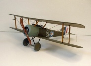
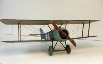
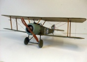
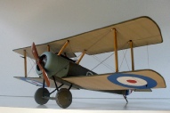
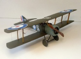
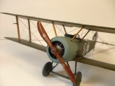
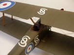
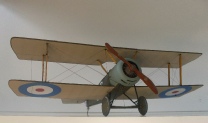
This model has been an absolute delight to build and full compliments must go to Wingnut Wings for producing such a brilliant kit. The ease of assembly associated with this kit would certainly make it a great contender for anyone wishing to start building WW1 aircraft and possessing only limited experience, but for the more experienced modeller it offers scope for super detailing and finishing. I have built this kit virtually OOB just adding a little extra detail inside the cockpit area, but there are no limits to what could be added. The rigging is very basic and can quite easily be tackled by anyone with little rigging experience. Like all Wingnut Wings kits, there is no rigging material supplied with the kit. I would have no hesitation at all in recommending this kit.
I must send a big word of thanks to James Fahey for sending me this kit and giving me the opportunity to share my build log with everyone else, I hope my build will help others who may find difficulty with some aspects of the build but it is such an easy kit to build I doubt if anyone will have problems. Contact me with any questions.

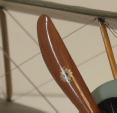
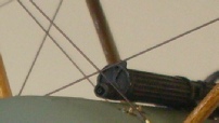
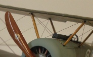


These two photos show the modified Lewis gun. I drilled a 0.4mm hole through the centre of the barrel to a depth of about 5mm. In the same hole I drilled using a 1mm drill bit to about 2mm deep. I then cut a piece of 0.4mm brass tube to the correct length then inserted it into the 0.4mm hole with the end result as shown in the photos, it looks a lot better than just drilling a hole in the end of the barrel.
The photo on the right is a close-
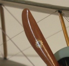


The undercarriage is now fixed in position, it has excellent locating pins and fits very securely, the undercarriage rigging adds a lot of extra rigidity to the assembly. As seen here, the flying wires which pass through (that’s the impression they give) the bottom wing and secure to the undercarriage legs are also fitted, fitting these was a little tricky as they are only very short, about 3mm. I glued 4 eyelets to the undercarriage legs then did the rigging in the normal way by adding brass sleeves, viewed from the front they line up perfectly with the flying wires between the two wings so the illusion is complete.