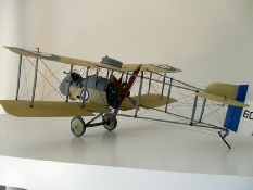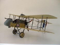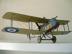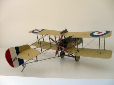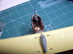
After the construction of this model my computer had a major melt down and I lost most of the recorded photos of the build. I managed to save what you see here so I will endeavour to fill in the gaps with a written explanation of what I did, I apologise for the lack of photographic records.

The engine supplied with this kit is not too bad, it would make up quite presentable without any intervention. I removed the valve springs on the top of each cylinder, I drilled a 0.5mm hole and inserted a short length of 0.5mm brass tube, I then wrapped the tube with 0.13mm copper wire to simulate valve springs, CA holds it all together. I added push rods and rocker arm assemblies all made from materials from my spares box. The rocker arms are copper wire flattened at each end, the end that takes the push rod was tapped lightly with the pointed end of a small nail to give a concave shape for the push rod to sit in, the other end was left flat to sit on the valve springs. The rocker arm support is another piece of copper wire flattened at the top then drilled to allow the rocker arm to pass through, it is then glued into a hole drilled into the top of the cylinder head. I also added spark plug leads.
The cockpit was built virtually OOB except for the seat, I made a wicker seat which was my first attempt. The nacelle was enhanced with two straps over the top made from 0.16mm plastic card cut into strips. I drilled 0.3mm holes either side of the strap and inserted U shaped copper wire into the holes over the straps then pushed them down until they rested on the straps. The stitching around the nacelle was painted on but at the end of each stitch I drill a 0.2mm hole. The original aircraft had a row of rivets running around the nacelle so to simulate this I drill a heap of 0.3mm holes at equal distance apart, I then inserted a piece of 0.3mm copper wire into each hole and trimmed them off leaving just a small amount protruding above the surface, this acts as a rivet. Around the top of the nacelle I glued a piece of soft copper wire to act as the rolled edge, this also extends down the front of the nacelle around the gun reinforcement plate.


I added cockpit padding using modelling putty and before it was fully set I pressed
in pieces of cut left over PE bent to a U shape to act as securing clips. I wrinkled
the fabric on the sides of the nacelle by filing with a small round file there is
no particular pattern for this, just random wrinkles but be sure not to over-


This photo shows one wing with the pre-

Once the top and bottom wing are completed the struts can be fixed in place, (do not attach the tail booms at this stage). These are very weak and require careful handling, make sure they are aligned with each other before fitting the top wing. With the top wing in place the whole assembly is very unstable so rigging should be done as soon as possible to strengthen the unit. For this model I used 0.17mm monofilament, I drilled half way into the underside of the top wing, fixed the mono with CA and I drill right through the bottom wing using a 0.3mm drill bit. I inserted each line through the hole in the bottom wing and using a small weight added tension to the line, a small drop of CA holds each line in place. Note that there are double flying wires fitted. Once dry, trim the excess line under the bottom wing. The whole wing assembly is now very strong and can handled very easily. The undercarriage can now be fitted and rigged making sure it is plumb with the aircraft.

So I could drill the holes straight I removed the four tail boom uprights by cutting
them flush with the tail boom with a very sharp scalpel. I then drilled a 0.2mm hole
through the brackets at each end of the uprights, make sure you mark the uprights
and the position they came from. Refit the upright and allow to dry thoroughly. The
tail booms can now be fitted to the wings along with the tail section. You will notice
that this assembly is very very fragile and will not take any mistreatment so the
sooner the rigging is attached the better. Using the same 0.17mm mono I rigged the
entire tail section making sure not to over tension the lines as it will pull the
whole assembly out of shape. Once the rigging is complete the tail boom section will
be very rigid. It is a very complex rigging set-
Finish the rigging by adding all the control lines to the wings and tail section. I added small cut pieces of left over PE to cover the union between the booms and top wing, it makes the end result more appealing to the eye.
As can be seen by this series of photos the rigging is very complicated and you can quite easily get lost in a maze of wires. It is so easy to cross wires unknowingly or to run one in the wrong direction all of which causes mass confusion and frustration. Thorough planning and plenty of time and patience will see the rigging all fall into place quite quickly.


Again, I must apologise for the lack of photos but I have done my best to describe the processes I took to complete this wonderful model. Roden has been criticised by many for it’s rushed approach in producing this kit but I found it to be a great kit, it has plenty of scope for those who want to do the super detail thing and I believe there are now after market PE sets for this model. This was a very enjoyable kit to build, it had it’s challenges but nothing that could not be overcome with a little thought, I would definitely recommend this kit to anyone who has moderate to advanced modelling skills.
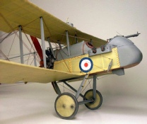
Below are some photos of the finished model which I hope will inspire others to build this kit.
