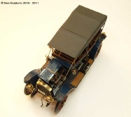
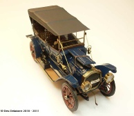
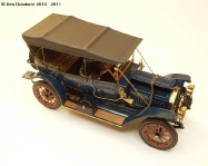
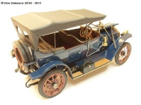
I chose the 1911 Packard Tourer as a vehicle to use with my aircraft dioramas. It is a very old kit purchased from Holland Plastic Model Cars, it was expensive but this type of model is very hard to come by and is no longer in production, hence the high price. This kit was moulded way back in 1967.
I hope to build this car with the bonnet open to display the engine. I will detail the interior of the vehicle with the limited resources I have available, I’m not a vehicle builder so fingers crossed that this will turn out to be a respectable looking model.

Kit contents revealed a very basic kit with parts all thrown loose in the box, the clear plastic parts have been marked due to years of being shuffled around amongst the other parts. The kit was advertised as having brass plated parts, there are none at all in the box, the rubber tyres are not very well detailed with tread pattern near non existent. Mouldings are not too bad but a lot of clean up is required and detail is pretty poor on some parts. There are no painting instructions at all so guess work is the order of the day.
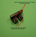
I started the engine by first removing the plastic moulded push rods and valve springs, they are a very poor representation of the real thing. The four blobs of plastic that are supposed to be spark plugs will also be removed and replaced with brass tube. The area around the intake and exhaust manifolds needs to be built up to accept the valve springs. The mounting bracket for the fan will be replaced with a more suitable looking item. I have found the black plastic to be very hard, nearly brittle, so care has to be taken when trimming away unwanted material.

I made the eight push rods from 0.5mm brass tube then wrapped 0.2mm wire around each one to simulate valve springs (11 winds). I cut very small lengths of 0.8mm brass tube, slipped it along the tube and used them to act as valve spring retainers. Once they are all in place I will hold them with a drop of CA.


Spark plugs are made from 0.8mm brass tube as the base, then a 0.5mm brass tube is inserted into the base to act as the insulator and lastly a piece of 0.3,, wire is inserted into the insulator to connect the plug leads to. Two brass plates were trimmed and sanded to fit the top of each cylinder then secured with CA. For ease of assembly, I drilled through the crankcase to allow the push rods and springs to pass up to meet the intake and exhaust manifolds. The cylinders are painted satin black and the crankcase will be painted aluminium. The length of the push rods will be trimmed once they are fastened to the cylinders and crankcase. As the bottom of the engine will not be seen it will not be necessary to repair the holes in the crankcase. Two holes are yet to be drilled in the top of the cylinders to take the water pipes from the radiator. I have photos of restored Packard’s so the accuracy of the detailing is open for debate.

I used the kit supplied water pipe, the brass bits are painted with gold leaf and the rubber hoses are painted a dark grey, hose clamps are painted with Humbrol aluminium. The exhaust valve caps are made from 1mm brass tube cut to a small length (about 0.5mm) and inserted into 1mm holes drilled above the valve springs. The row of small “bolts”around the brass plates on the cylinder heads are made from 0.3mm brass tube inserted into 0.3mm holes drilled through the brass plates, they are held with CA. (16 bolts all up). The kit oiler is painted with Gunze copper and the small fittings on top of the oiler are painted with gold leaf.
I am not going to go overboard with the amount of detail on the engine, I will be adding the magneto and plug leads, plus the tube the plug leads run through. I will also improve the kit supplied radiator fan and pulleys and will add a fan belt.
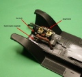


The engine temporarily fitted to the chassis. I made a magneto from scrap bits on hand and fitted the plug leads (0.13mm copper wire painted with Humbrol No. 100 red/brown), the leads run through the brass plug lead tube secured with a bracket to the cylinder head. I made a fan support and fitted a pulley behind the fan, plus a pulley from the crankcase then fitted a fan belt, this is very simply made from a piece of paper cut to the correct width, it was then fitted around the three pulleys and glued into place, I then painted it with dark grey. An oil pipe from one of the cylinders was also added by using copper wire. I don’t know what the thing is standing behind the rear cylinder but it is in the photos of original cars, so I added it. Once the firewall is fitted there will be more plumbing and electrical wiring.


Photo on the left shows an oil can I made from scrap pieces, it sits inside the engine compartment as shown in the photo on the right. I also added some more plumbing which goes from the apparatus on the floor of the engine bay up through the firewall, it runs behind the exhaust system. Engine bay and firewall have been painted with Humbrol Polished Steel and buffed to a semi gloss finish.
The last photo shows a size comparison of the oil can that I made, the handle is made from PE fret material and the tube is 0.4mm brass tube, the body is shaped from a piece of plastic sprue and a small plastic disc glued to the bottom.


This wooden box mounts onto the firewall inside the cabin. The box is made from timber and stained with Jarrah wood stain. The switches are made from left over bits and pieces and painted with gold leaf. The completed assembly was then sprayed with Humbrol Gloss Cote.


These two photos show the cabin interior. All instruments are made from brass tube with decal instrument faces, a drop of clear gloss acts as the glass. The two switches on the box are made from scrap plastic and brass tube.


I made the foot pedals from 0.5mm brass tube bent to shape then flattened, the foot pads are made from left over PE fret material, CA holds everything in place. The brass edgings around the foot pedal cut out slots are made from 0.18mm brass wire bent to shape then held in place with CA. The floor edging is 0.3mm brass tube glued into position. The first photo shows the scratch build switches and the instruments very well, also the wooden box. Where possible I prefer to make my own details instead of buying after market accessories.

I’ve started work building the gear and brake levers. I used 0.6mm brass tube for the levers and fitted small brass washers for the hand stops. The small ratchet release lever is made from left over PE fret material super glued to the lever. I still need to make the gate which will mount on the floor.
I made the brake and gear lever gate from scrap bits of brass. The main body is from flattened 0.5mm brass tube, I filed two small indentations to allow the levers to fit in the gate, I applied CA to hold it all in place. The small wire used as the ratchet release connection is a worn out 0.2mm drill bit.


The kit supplied steering wheel is a very poor representation of the original wheel, so I will attempt to make a new one. I have removed the spokes and will replace them with thin brass sheet the appropriate width. I will utilise the kit hub with modifications to suit the new spokes. I also removed the steering column and fitted a 1.5mm brass tube. Ignition advance/retard lever will be fitted to the completed steering wheel. The steering wheel rim will be wood grain.

This is a trial fit of the unfinished steering wheel. I have fixed the spokes to the hub and the outer rim using CA. A 0.1mm hole was drilled through the hub to take the pin in the steering column. The ignition advance/retard lever still needs to be added along with the guide rail for the lever, this will span three spokes. The outer rim will be timber look while the spokes will be metal.


Two photos showing the near completed steering wheel. I will add oil paint to the rim over the base coat of acrylic to simulate wood grain, then a coat of gloss clear.


The rubber tyres supplied with the kit are very crude with a lot of clean up required. The rims come no where near fitting so I had to trim away the inside ridge, I used a very sharp scalpel blade. The outer portion of the inside of the rims have a moulded rounded section which holds the rim away from the tyre, I removed this section with a fine round file. The photo on the right shows the result of all the modifications, the rim sits well within the tyre with no gap between the rim and tyre. The inside rim will need to be thinned a little to allow both inner and outer rim to be glued together and hold tight against the tyre.


These two photos show a mock up of the car with the interior components added. The steering wheel is now completed but is only sitting loose on the steering column. The right side engine bonnets will be fixed closed and the left side will be left in the folded open position.


I have added the rim/tyre locking plates with bolts to one of the wheels, three to go. I used the nuts from the Vectorcut nut and bolt set with one side trimmed a little so it had a flat surface to sit against the rim. Once they where super glued in place I drilled a 0.5mm hole through the rim and fitted a small length of 0.5mm brass tube to simulate the bolt. The photos show the unpainted wheel with the completed locking plates and bolts. The Vectorcut set is brilliant, it is laser cut on circuit board, it is very easy to cut with a sharp scalpel blade and adheres very well with CA. The hub of the wheels required some clean up, there was some flash that needed removing from between the spokes, quite a simple job.


Here are the four wheels nearly completed. All the locking plates are fitted, the rims are painted with Humbrol No.133 Satin Brown, the locking plates and rim centres are painted with black printer ink, once dry a coat of Humbrol Matt Cote protects it all. Photo on the right shows the rims just sitting on the tyres to give an idea of the final appearance.

This kit was advertised as having brass plated parts, it didn’t, so I have sprayed the parts with Humbrol Gloss black in preparation for the Alclad Polished Brass. I have also painted the seats with a base coat of Gunze yellow then Raw Umber oil paints, they are in my heat box drying.

The wheels are now fixed to the axles and painting has commenced. I made a swivel handle for each tool box and fitted them with CA. I also added a brass edging strip to each running board by using flattened brass tube, CA holds it in place very well.


I have sat the unpainted body in position just to see how things are going to fit, the seats are also just sitting loose. The seats were firstly painted with Gunze Yellow then I used oil paints. I used Raw Umber and with a small stiff brush I stippled the surface, when dry I sprayed a coat of matt clear then I went over the seat again with a very diluted mix of Raw Umber, once it is dry again I will spray it with a coat of Humbrol Satin Cote. For an old kit the seat detail is not too bad, the lack of buttons spoil it. The radiator has been painted with Alclad polished brass and positioned just for photo purposes, the Alclad paint is pretty good and gives a fairly good result, not as nice as real polished brass but for a paint finish it is passable. Once the body has been painted I will be adding door handles to the outside of each door.


I have painted the remainder of the brass bits using the Alclad polished brass again, as you can see by the photos they turned out pretty good. I have fitted the headlights, side lights, tail light and windscreen frame. I fitted a clear acetate sheet for the windscreen glass, the kit supplied clear plastic part was badly scratched and was way too thick. Because this vehicle used acetylene lighting a tank was needed, so I made one from a piece of brass tube with the rounded end being shaped from miliput, the pipes are copper wire.


A collection of photos showing the near completed car. The main body is now fixed as well as the seats. I made door handles from 0.18mm copper wire painted brass and fixed to each door. The dark blue colour is complimented by the brass and the brown leather seats also fit in well with the colour scheme. The seats have been sprayed with Humbrol Satin Cote, gives a nice polished leather look.


The ‘roof’ is now on, it has been sprayed with Gunze tyre black. The roof support frame was ¼ inch too short and would not reach the body, so I discarded them and made new frames from 0.8mm brass tube, one end was flattened and a 0.4mm hole drilled, a length of 0.4mm brass tube was glued into holes drilled in the body then the frames fitted over the 0.4mm tube, the other end of the frame was attached to the roof. The windscreen support rods are made from 0.6mm brass tube, the kit supplied plastic rods were too large in diameter and out of scale. All the roof frames and the windscreen support rods are held in place with CA. I am now working on the spare tyres which will mount on the back of the vehicle and the bonnet, half the bonnet will be in the open position to display the engine.

The spare tyres have been fitted to the back of the car. I used the best of the tyres for the car, the two on the back are very poor mouldings, very crude tread pattern and a rough texture with holes in the moulds. The brackets and belts are pretty good and the buckles are depicted fairly well.
PHOTOS OF THE COMPLETED MODEL
I completed the model by adding the half open bonnet (hood), a lot of sanding was required to get the two halves to sit reasonably flat. I also made and fitted the handles for the bonnet, they are made from 0.3mm brass tube bent to shape. As the bonnet is open the tie down strap is loose so I added it for affect, it is hanging loose over the bud guard (fender) and hanging down into the engine bay. I also added a small lens to each of the side lights, this was cut from a piece of clear sprue material. This kit, although being very old and lacking detail, was a joy to build and ended up looking pretty good, it was a nice distraction from my usual aeroplane builds.


