
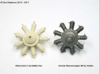
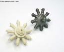

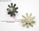
The BA (Battle Axe) resin engine is not too bad but I have decided to use one of Rodens Gnome kits.. I had already starting work on a Roden Gnome so have decided to modify it to make it look a little like the Oberursel U.I engine. The main problem with both the BA and Roden engines are the size of the cylinders, they should be a lot bigger in diameter, where they meet at the crank case should only be a small gap with a small flange and bolt.
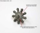
The first task was to remove all the moulded detail on the face of the crank case, this was done very carefully using a very sharp scalpel blade then finishing off with a fine grit sanding pad. New details need to be added to represent the Oberursel engine which was different to the Gnome engine.
I drilled a series of 0.4mm holes into the crank case front to allow me to insert 18 small Grandt Line nuts/bolts to represent the crank case bolts. It is important to get the bolt spacing correct so they look symmetrical. The Oberursel engine had a small raised section on the face of the crank case just below the row of bolts, I did this with a piece of 0.25mm copper wire wrapped around an 11.0mm tube to get the correct size, once in position I used CA to hold it in place. The photo shows the Grant Line nut/bolts that I used, they are well made and very easy to use, they are also inexpensive to purchase. The shaft on these bolts are a perfect fit into a 0.4mm hole and they hold extremely well with a very small drop of CA.

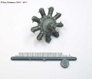
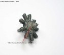
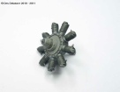
I used the cam follower section from the Roden kit by firstly removing all the push rods, these were way over scale. I then reduced the diameter of the section by turning it down, I then drilled the 9 cam follower holes by using a 0.6mm drill bit, the holes are evenly spaced around the section, I then fitted this section and drilled the holes through the crank case front section.

I removed the front section of the engine forward of the cam follower area, I did this with a fine tooth razor saw. I then turned a piece of sprue plastic to a tapered shape to represent the propeller shaft, this I inserted into the hole which was exposed after removing the front section, plastic glue was used to hold this in place.
I utilised the front section of the crank case from the BA resin engine by cutting it off with a razor saw, I then drilled a hole the correct size so it would slide onto the new propeller shaft. I also reduced the diameter of the larger size by turning it down just a little, it is not glued at this stage as all the bolt holes need to be drilled.
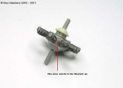
As can be seen in the two photos the two rows of holes are now drilled. To keep the spacing correct it is a simple matter of placing the drill bit next to the existing nut, drill all the holes then remove the moulded nuts, doing it this way you will end up with all the holes evenly spaced.
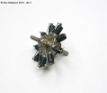
I have fitted all the Grandt line nuts and bolts to the forward section of the crank case, this has also been attached to the propeller shaft. The spark plugs on the Roden engine are not in the correct position, they need to be more towards the rear of the cylinders. I removed all the moulded spark plugs and drilled 0.4mm holes on the same line but back more towards the rear, as you can see the spark plugs are sitting in their cylinders but not at this stage fixed. The plugs are made from 0.4mm brass tube, a small rbmotion brass nut is slipped onto the tube and CA is used to hold it in place leaving 1.0mm of tubing protruding above the nut, I am also placing a very small brass washer below the nut where it butts up against the cylinder. The engine is now starting to take on the appearance of an Oberursel U.I rotary engine.
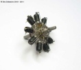
The cam followers are made from 0.6mm brass tube with a small brass washer sitting on the crank case, the push rods are 0.4mm brass tube with a small brass washer sitting on the 0.6mm tube, push rods and rocker gear is painted with Stainless. The brass engine identification plate is from the Roden Gnome kit. The cylinders are painted with Gunze tyre black and the crank case is painted with a mix of Mr. Metal Color Aluminium and Brass. I made a ring to fit at the back of the engine to take the ignition leads, it has been painted with Gunze red/brown. The insulators on the spark plugs are painted with Humbrol Gloss White, I will be fitting the ignition leads next.
I used 0.13mm copper wire for the ignition leads, CA holds them in place. The engine is now completed, it is not exactly the same as an Oberursel U.I but it is fairly close, considering it started off as a Gnome it didn’t turn out too bad, once fitted in the aircraft only the bottom few cylinders will be seen in full view.


I am making a new fuselage frame forward of the bulkhead which sits behind the pilots seat. I removed all the moulded frame and bracing wires then made the new frames from 0.8mm brass tube. I drew a template then placed the tube onto my drawing taping it down to hold it in place, I then used CA on each joint. Once the glue was set I turned the frame over and applied CA to all the joints again, this ensures a good bond. The photo on the right shows one of the frames sitting on the fuselage side. I will be making these frames as a box section and when fitted with all the cockpit items it will be fitted inside the fuselage, hopefully it will slide into the fuselage neatly. Using CA to hold the frames together is reasonably strong, not as strong as solder but strong enough to withstand handling, it will not react well to rough treatment.
I’ve added the two sliding hatches, one each side of the fuselage, they are made from thin brass sheet with 0.4mm brass tube as the runners, the handles are made from flattened 0.3mm brass tube then shaped to represent a handle.
I have been experimenting with the swirl effect for the hand burnished aluminium
side panels. I firstly sprayed the sides with Mr Metal Color Stainless, I allowed
it to dry for at least one hour. I then used a cotton bud (Q-


The bracing wires are cut to the exact length and CA’d to the frame. On this aircraft the turnbuckles were wrapped in what looks like a leather sheathe, so to simulate this I first applied some Mr Surfacer 1000 to the wire, when dry I painted it with Humbrol Leather. The pressure pump supplied with the kit was garbage so I made a new one from 1.2mm brass tube. The rear bulkhead has been fitted with the highlighted stitching and a few creases in the fabric.

I am improving the undercarriage struts by reducing their size in width and thickness.. I cut the suspension swing arm assembly off the struts using a razor saw, I then opened up the plastic below the swing arms by drilling 0.4mm holes then cut out the remaining material with the razor saw. Into the ends of the arms I drilled 1.0mm holes then inserted 1.0mm brass rod which has been bent to the appropriate angle. I will drill 1.0mm holes into the top of the undercarriage legs and they will fit onto the brass rods, this will make a strong assembly.


The kit supplied control column is very basic, it looks nothing like what it is supposed to, so I made a new one. The column is 1.0mm brass tube, the ring is made from 0.5mm brass rod shaped around a 4.0mm drill bit, the curved connecting piece which holds to ring to the column is 0.9mm steel wire. I made the hand grips from 1.0mm plastic tube, I cut it down one side then slipped it over the ring, CA holds it in place, the ends of the plastic tube are filled with paint to give a rounded shape. The trigger is made from a 0.4mm brass tube with a 0.13mm copper wire threaded through it, this wire is bent down and then cut to length, a piece of left over PE was cut to size then glued onto the two 0.13mm copper wires, this now forms the trigger. The top section of the control column is painted with Gunze tire black, the column itself will be painted the same grey as the fuselage frames. As per photos of the exact replica the trigger pad is painted red, the letters MG should be painted on the pad but my hands and eyes are not up to that exercise. The second photo shows a good comparison between the kit column and my hand made item.

This photo shows the suspension swing arms in place and the bungee cords painted. Also fitted is the control column actuating rod and the connection to the swing arm. The floor has been wood coloured using oil paints over a base coat of Gunze acrylic.


The port side fuselage frame is now fitted, it is CA’d to the floor and bulkhead. The control column is also fitted, I drilled a 0.6mm hole onto the actuating rod on the floor then inserted a 0.6mm brass tube into the bottom of the control column, this was CA’d in place then the column was fitted. I made a small instrument to fit on the right side of the cockpit, I also made the seat supports and fitted them to the bulkhead and the floor, the legs for these supports are made from 0.4mm brass tube. I also fitted cables from the control column running back through the bulkhead under the seat.

The fuselage has now been buttoned up, surprisingly it closed up very well with very few gaps or misalignment, the fuselage frame fitted perfectly to the left side of the fuselage.

Fitment of the firewall (bulkhead) revealed that the firewall is not round in shape and the locating hole for the engine is not in the centre. I will need to sand the firewall, more so on the right side to get it to sit correctly in line with the rest of the fuselage. The firewall located onto the fuselage frame very well and the two cheek blisters fitted well but do need a little filler. The photo on the right shows the engine temporarily fitted just to give me an indication of how far the hole is off centre, this will be a reasonably easy fix. The upper decking forward of the cockpit required a 1.0mm reduction in height, sanding this from 6.0mm to 5.0mm also reduced the width of the decking which when completed fitted the fuselage perfectly, this modification was called for in the instructions.


The kit upper rigging mast was out of scale and too bulky so I made a new one by using 1.2mm brass tube, I inserted a length of 0.46mm brass wire through the tube then flattened the tube using a pair of smooth flat jaw pliers, this gives an aerodynamic shape to the mast, once flattened I removed the wire. The two lengths were cut so when assembled there was a 12.0mm gap from the decking to the top of the mast. I drilled 0.5mm holes into the top of the fuselage sides and glued 0.5mm pins into the bottom of the tubes, this gives a positive locating point. I needed to file the sides of the decking to allow the frame to angle inwards without fouling on the decking.
I also assembled the rigging pulley from the PE set supplied with the kit, is made up very well and when fitted to the mast looks extremely well, when painted will look the part. I added two short lengths of brass tube to make it easier for fitting the rigging.
I drilled out the instrument shield on the decking with a 2.0mm drill bit, then I cut a length of 2.0mm brass tube, fitted an instrument dial, this becomes the instrument. I removed the two moulded fuel filler pipes, these will be replaced with brass tube and the kit PE caps. The PE machine gun feed and exit chutes have also been fitted, these came with the PE set. I also drilled two 0.4mm holes in the decking to take the rigging wires. The engine is only dry fitted just to give an indication to what it is going to look like.


I discarded the fuel control panel from the PE set and made my own. I used a piece of brass sheet for the board, I added an instrument face then added an instrument bezel. The fuel control levers are one sided wing nuts cut down and fitted into a 0.4mm hole. I fitted a 0.35mm copper wire into the bottom of the pressure pump and ran the wire up so it fits behind the fuel panel, there is also a piece of 0.13mm copper wire running from the instrument and then behind the panel. There is another instrument on the other side of the cockpit, this is made from brass tube with an instrument face inserted into the tube, the switch above the instrument has a lever fitted as well. The rudder bar is fitted as well as the rudder control cables, they have been painted with Mr Metal Color Stainless.
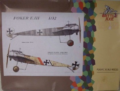
This is a limited run kit and like most limited run kits it has some issues with moulding quality, misalignment of the moulds, flash and pin marks. The parts are on one large sprue moulded in a light grey easy to work plastic, my sprue was missing the machine gun. There is an excellent PE set with finely detailed parts on a thicker than usual brass, these parts are easy to remove and simple to bend. Even though there was a windscreen on the plane there is none supplied, but there is a template. The decals appear to be okay but time will tell, the colours look good. The instructions are very basic and in places a little difficult to understand. The biggest issue are the wings, there are only 12 ribs per wing where there should be 13, if left as is it would not be very noticeable but to keep it in scale the ribs will have to be altered. This is a kit that is definitely not for the beginner, a modeler with moderate to experienced skills will still find it a challenge but will end up with a nice model of the Fokker E.III

I completed all the filling and sanding along the seams of the fuselage, there was not a great deal to do. I also corrected the out of shape engine firewall/bulkhead by sanding one side and bulking up the other side. The entire model was sprayed with Humbrol No.1 primer and allowed to dry over night, it was then sanded with 1200 wet and dry paper (dry) and dusted off.

The fuselage has been painted using Hobby Color H313 Yellow FS33531, the fuselage
frame pre-


I utilised the main undercarriage struts and the rear mast but replaced the remainder with 1.0mm brass tube. The tube was inserted into 1.0mm holes drilled in the appropriate places on the undercarriage assembly. I used the PE parts supplied with the kit for the rigging attachment points, one at the front of the assembly and two at the rear, these are pinned with a short length of 0.6mm brass tube, everything is held together with CA. The whole undercarriage unit is only sitting in position at this stage, I need to paint the forward part of the fuselage before it can be fixed in position. Building the undercarriage in this manner has made it a very strong unit, it will be even stronger once the rigging is attached.


Very hard to see here but the fuselage frame shading is done, it was applied using a lead pencil and then lightly misting the CDL colour until the desired look was achieved, in these two photos the fuselage has been gloss coated ready for the decals. The undercarriage has been painted and is sitting loose, the wheels are also sitting loose. I drilled the centre of the wheels and glued a piece of 2.0mm brass tube into each wheel, this slips over the axle very neatly. The tail skid is also fitted but unpainted at this stage, I used the kit tail skid but the support arms had to be replaced, I used brass rod shaped to match the discarded plastic items, the engine is also displayed just for show.
I’m doing this model to depict Fokker E.III 105/15 -


The red and black fuselage bands are cut from left over decals, the other decals are the decals supplied with the kit. I cut the decals from the decal sheet cutting as close as possible to the decals, I was a little wary of the quality of the decals and wanted to avoid silvering. The decals went on very well and sat down nicely with the help of decal set solution (Mr Mark Softer) and a hair dryer. The entire fuselage has now been sprayed with Humbrol Matt Cote, this not only protects the paint but seals the decals and gives a nice finish.


The wings when compared to the scale plans are 5.0mm too short in length, width is okay. To add the extra wing rib to the existing wing length would put a rib too close to the wing tip, or to start at the correct location at the wing tip rib and move inward the ribs would be too close together. The wing could be lengthened which would involve a fair bit of work and then the 13 new ribs fitted, or it could just be left as supplied. As this is more of a kit review I will be leaving the wing as is, the missing rib and the shorter wing length will not be very noticeable, only the die hard rivet counters will criticise the error. Once the wing is fitted, painted, decals on and rigging fitted it will certainly look the part and will not be a glaring fault.
The undercarriage is now fixed in position, the engine is fitted as is the engine cowl and the rudder is also fixed. I had to elongate the mounting hole for the engine as it sat too far to one side because of the off centre hole, only about 1.5mm needed to be taken out. The undercarriage fitted beautifully and is very strong. The photo on the right shows the front of the fuselage with the swirl marks, subtle but visible.


The machine gun is a left over Wingnuts gun with the Master Spandau LMG 08/15 brass and PE accessory set added, the gun sight is from the Battle Axe PE set, it was painted with Mr Metal Color Dark Iron then lightly buffed. The feed and exit chutes are from the kit as is the bullet belt. The upper mast is now fitted and I added the fuel and oil filler caps to the front of the upper deck. The main fuel filler tube and cap is also added just behind the cockpit, this was made from brass tube and I utilised the kit supplied PE cap. The padding around the cockpit was made up with layers of Mr Surfacer 500 and finished off with Mr Surfacer 1000. I’m still waiting the arrival of the seat belts which are coming from HGW (Battlefield). I have fixed eyelets to the underside of the fuselage ready for the undercarriage rigging and holes have been drilled for the elevator and rudder control rigging.
I used 0.12mm monofilament for the undercarriage rigging connected with 0.4mm brass tube sleeves, it is all held together with CA, the rigging has been painted with Mr Metal Color Stainless. I also added the first two rigging lines to the upper mast, these are also 0.12mm mono painted with stainless. I added turnbuckles to each line, these are made from 0.5mm brass tube with 0.13mm twisted copper wire for the eyelets, the little brass sleeves are 0.4mm brass tube drilled out to 0.3mm. The windscreen is a left over screen from another kit but is fairly close to the right size, it is only small so would not offer the pilot much protection. The propeller shown here is only a temporary fitment and may not be the one being used for this plane. The paper around the fuselage is there to protect the paint and decals during handling, constant picking up and handling of the model can lead to dirt marks or even scratches on the fuselage.







I used the kit wheels, the rubber tyres are a bit thin but they look okay on the model. The wheel covers are painted with Gunze 313 yellow and the tyres are done with Humbrol No.92, the prop is only a temporary fitting.


The trailing edge of both wings were very wavy but was easily fixed by clamping and then pouring boiling water over it followed by cold water. The leading edges took more effort because of the thicker section and the extent of the warp/bow, up to 2.0mm near the wing root, again, clamping onto a solid piece of timber then pouring boiling water over the trouble area rectified the warp/bow. On one wing there were three places where holes had been torn from the leading edge, this was caused when the wing was ripped from the sprue I presume during transit, these holes have been filled and will be sanded after over night drying. The clamps I used to fix the wings are now useless, the boiling water melted the plastic jaws and they no longer have tension, luckily they were very inexpensive.

The wings are now bow free and have been painted with Mr Hobby Color 313 yellow.
I will be applying the pre-


The holes in the side of the fuselage are far too big for the locating pins, so I have filled them with plastic round stock. As can be seen in the photo the locating pins on the wing are very small so I will remove them and put pins in the fuselage and holes in the wings.


The white squares on the wings have been painted with Gunze matt white and once dry a coat of Humbrol Glosscote was applied in readiness for the decals. I did the prop firstly with a base coat of Gunze yellow then the wood was done with artists oils, the hub is painted with Mr Metal Color Stainless.

I drilled a 1.0mm hole through each of the four plastic plugs making sure there were no obstacles in the fuselage to hinder the brass tube passing through to the opposite side. I inserted a length of 0.6mm brass tube first, this will act as a guide, I then slipped the 1.0mm brass tube over the smaller tube and slide it through the fuselage, the guide tube helps line the larger tube up with the exit hole. Once I was happy with the result I marked the tube, withdrew it, cut it to length then repeated the procedure, I positioned each tube so there was equal length either side then I added a drop of CA to all four points, I now have very solid mounting pins for the wings to slip onto. I will next mark the wings and drill 1.0mm holes to the appropriate depth.


I positioned the wing over the pins and marked their location, I then drilled 1.0mm holes (two in each wing) to a depth deeper than the length of the pins. The leading edge hole was easy to drill as there is ample thickness in the wing, but the trailing edge hole was a little more difficult as there is only just enough thickness in the wing to take the 1.0mm drill bit, one wing was actually thicker in section than the other. When drilling these holes it is very important to make sure the holes are dead straight in relation to the wing, any deviation could lead to the drill bit breaking through the surface of the wing. The wings slipped onto the pins beautifully and as seen in the photos the wings sit reasonably level, there is no glue holding the wings at the moment so it goes to prove the strength of the brass tube pins, it would be impossible to achieve this result if I had used the existing pins. The wings will now be removed and completed before they are fixed permanently.
COMPLETED MODEL
The wings were fixed using CA on the pins and the wings pushed on very quickly. All the rigging is done with 0.12mm mono painted with Mr Metal Color Stainless, the rigging helps to keep the wings parallel. All that remains is the seat belt which has not yet arrived. The rigging on the upper mast is done in accordance with period photos so it is pretty close to what the original aircraft looked like. I hope you enjoy the photo collection below, it turned out to be a nice looking model.


This model has had a very bad reputation as being a real dog of a kit, it has it’s faults but then so do all models. There have been some pretty bad reviews and builds done but I have found this to be an enjoyable build, it turned out to be a very nice looking E.III and it sits very well amongst all my other 1:32 scale WW1 aircraft models. I would not recommend this kit for a novice builder but anyone with moderate to experienced modeling skills it would suit them perfectly.
 Index
Index