


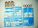

I plan on converting the old Pyro (1967) T Model Ford pie wagon into a Huck starter. The Pyro kit is very basic with a lot of work needed to make the vehicle look anywhere near respectable. The moulding on the parts is quite faint on most parts so some enhancement will be necessary. The kit has vinyl tyres and clear plastic parts for the windscreen, the clear parts will not be needed. The instructions are printed on one side of a small sheet with directions being basic to say the least. The Huck Starter was a very crude vehicle which consisted little more then a chassis, an engine and a mudguard. Some variations of the Huck starter included the shielding of the chain drive to the top sprocket, probably a wise move considering how close the operator sat to the mechanism. If it all works out this vehicle will be used in my diorama.
I started work by making the rear axle, diff and spring assembly. I added bolts to the diff housing and also to the outer ends of the spring. I also added the box which sits on top of the diff housing, this was sourced from my spares box, it’s actual purpose is unknown to me. I painted the unit using Humbrol No.31 Slate Grey. The parts so far went together fairly well, the brake drums could be better depicted.

This is the kit supplied front axle and suspension assembly, it is totally wrong and will have to be virtually scratch built. This will be my next task so it could be a lengthy operation.


I managed to make a whole new front suspension assembly from material in my spares box. The new leaf spring is a left over from the Wingnuts Hansa Brandenburg W29 kit which just happened to be the correct size. I still need to add the wishbone assembly plus a few other little bits and pieces. What I have here is now a much better representation of a T Model ford front end.


The front suspension is now fixed in place but the rear is just sitting there for photo purposes. I will need to assemble the engine and fit it before I can progress much further. The engine is again only very basic, if I decide to leave the engine covers off I will have to do a lot of detailing otherwise I can just paint it and cover it with the engine covers.


The wheels are now fitted. The tyres supplied with the kit are not too bad and will look okay once the vehicle is finished. The tyres are a tight fit onto the rims so no glue was needed to hold them in position. I added the rim retaining bolts around the outer edge of each wheel, I drilled 0.4mm holes and fitted Grandt Line bolt sets, hard to see on these photos though. I painted the valve stems with a brass colour.


Major surgery was need to remove the two front mudguards and running boards, these two parts are all that is need for this particular vehicle. I cut the unwanted section using my Dremel leaving a small amount of material for fine sanding. I will need to make mounting brackets which are bolted to the chassis and hold the running boards.


I have painted and fitted the two front mudguards, I also shortened the running boards, stays need to be fitted to the running boards. I glued all the engine covers together then fixed them to the radiator and the firewall. The firewall is all that was fitted to the Huck starter, a small instrument panel will be fitted along with a few other accessories. The engine will be painted but not detailed as none of it will be seen except for the sump. Surprisingly, all the parts so far are fitting quite well, the only issue is the front suspension/axle assembly, it is quite weak and the wheels could break off easily if mishandled. The engine covers will be painted today along with the engine.


Engine covers are now fitted and painted. I also added mudguard stays, these are mode from 0.6mm copper wire bent to the appropriate shale then Super glued in position. The radiator grille is painted with Gunze tyre black and the Ford badge with Mr Metal Color Stainless.


I used the kit supplied cowl but cut it down substantially so it ended up the same size as the fire wall, I needed to fill the bottom section with plastic card. The fire extinguisher is from my spares box, I just made the handle and plunger rod. The small volt meter is from the Airscale WW1 decal set and the small brass bezel from the Aeroclub bezel set. The centre switch is a piece of plastic rod with a small one sided wing nut fitted as the switch lever.


I made the body from 1.0mm styrene sheet cut to shape then glued together using plastic glue. As I had no actual dimensions for the body work it was all taken from photos and a lot of guessing. The wood panels on the floor of the tray, the seat and the front platform were done using a very sharp metal centre point from a compass. The simulated punched nail holes are done using a 0.3mm drill bit. The strengthening timber pieces on the rear corners of the tray and also along the side are done using 1.0mm x 1.0mm styrene strips. The top boards on the front section were done by using 0.5mm x 2.5mm styrene strips. The rear tray is only very narrow as is the drivers seat but going by the photo reference I have this is how it was made.


A coat of paint changes the appearance dramatically, it brings out the details and ties the whole vehicle together. Next task is to make the rear mudguards and to fit the steering wheel, the body is now fixed to the chassis.


I have made and fitted the two rear mudguards, they were quite simple to make from styrene sheet. The mudguard support rod runs right through the tray as per original photos I have seen, an unusual arrangement. I also fitted the steering wheel, I used the kit supplied wheel but replaced the oversize shaft with a length of brass tube. I have also started to fit the floor boards, the forward floor will be sloped downward with the control pedals and gear lever, there will also be a hand brake lever. As I said earlier, the front wheel and suspension assembly is very weak, I have broken one of the wheels off three times already.


I made the floor from plastic card and scribed the boards using a sharp compass pointer. I cut the three slots for the foot pedals by drilling 0.5mm holes first then cutting out the material with a sharp scalpel blade. The foot pedals are made from brass tube, I flattened one end then bent it at ninety degrees and sanded the outer edge to a round shape. The pedals were then glued into the slots with CA. The hand brake lever was made with 0.8mm brass tube, the hand grip section is a length of 0.5mm copper wire inserted into the main tube. The ratchet lever is from 0.5mm copper wire flattened then bent to shape, it was glued to the main shaft with CA. The ratchet lever operating rod is a length of 0.4mm brass tube glued to the main body. I drilled a 0.8mm hole into the floor and glued the hand brake lever in place, a length of 0.4mm brass tube will connect to the bottom of the lever and run back to the rear wheels.


The frame work for the starting gear has been made and fitted, I made it from various sizes of brass tube. I had to make a mounting bracket which fits just forward of the seat on the side of the body, this supports the main frame member. The bracing rod tube which runs towards the rear is bolted the the side of the tray. The top bar needs to have a rope tied to each end, this is used to raise and lower the drive shaft which couples to the propeller. There still needs to be two crossed bracing tubes at the front of the vehicle, these will support the drive shaft, they are fixed to brackets mounted on either side of the front body. All components to make the frame assembly are held together with CA, it makes quite a solid assembly.

The gear, or sprocket, was made from a piece of plastic 1.00mm thick cut into a circle. To simulate the teeth I cut a strip just over 1.0mm wide from the top of a Pepsi bottle, these tops have very fine grip grooves so they were perfect for what I wanted. Once I cut the strip I cut it to length and CA’d it to the circular plastic, once dry I sanded both sides so it was the same 1.0mm thickness, a coat of Mr Metal Color Stainless finished it off. The top bar has a pin through it to act as a pivot so is a functional item.


Just to check to make sure that I had the height correct for the frame I did a mock starting scene. I used my SE.5a as a trial as the photos I have show the Huck Starter coupled to an SE.5a. The angle of the drive shaft is fairly close to what the photos show so I am happy with the results.


These photos show the remainder of the starting mechanism completed and fitted. All the tube was a variety of different size brass tube. The coupling at the front is made up from my spares box using left over bits and pieces of plastic parts, the bearing along the drive shaft is also made up from my spares box. The “rope” which is supposed to represent bungee cord is made from knit in elastic thread while the support at the front which connects to the bearing is made from a short length of 0.18 copper wire.


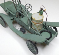
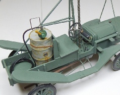
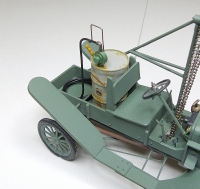
All parts have now been painted, all that is left to do is to find a roller chain for the main drive. I also made a battery and fitted it to the left side of the vehicle, this was made up from styrene sheets and the electrical cables are lead wire. I made and fitted the lever to actuate the drive form the gear box to the prop drive gear.


The Huck Starter coupled to the SE.5a in a simulated starting procedure. The addition of a few ground crew figures would complete the scene.


After a lot of searching I finally stumbled across a chain which will be suitable for the main drive. This chain is from Top Studio, the chain is 1:12 scale and is designed as an aftermarket chain set for a Hasegawa 1:12 scale motor bike kit. The chain is mainly PE and has metal rollers, each individual link has to be assembled using side plates and rollers placed onto a jig which is supplied with the kit. The short length of chain in the photo is the result of one session assembling the chain, this is the limit of the jig. There are enough materials in the set to produce eight lengths of chain, for the Huck Starter I will need five lengths. Each length of chain will be joined using the same links and rollers to produce one continuous length of functional chain. This chain is just a tad over scale but in this situation it will be appropriate, the Huck Starter used a large heavy duty chain. Motor bike rear wheel sprockets are included with the chain set but they are too large for the Huck Starter, the engine sprockets are too small. I will contemplate my course of action once the chain is completed.


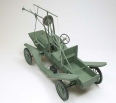
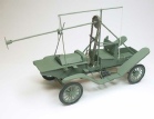
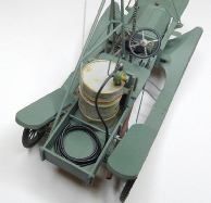
I completed the assembly of the Top Studio 1:12 scale chain set. This is a very highly detailed chain and the set contains tiny parts, this alone makes it a very difficult chain to assemble. It took me about two hours to assemble each short length of chain, I needed five lengths to complete the Huck Starter. I joined all five lengths then fitted the chain to the sprocket, I drilled holes in the floor to allow the chain to drop through and adding tension to the chain, super glue holds it to the sprocket very well. Once tension was applied to the chain I applied super glue to the chain where it passes through the floor.
 Index
Index