


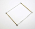

I have started this build by making the front engine support and undercarriage support structure. I have used 1.2mm brass tube for the main supports and styrene strips for the upper and lower timber supports, the two vertical timber supports are also from styrene. All the small accessory pieces are made from various sizes of brass tube and plastic tube. The assembled photo shows how the unit will look, the top and bottom clamps are fixed in position while the two centre slides are the ones that will take the undercarriage and allowed to slide up and down, springs will be connected to either side to offer suspension for the undercarriage. A very simple but very effective construction which not only adds a lot of strength but good suspension as well, it also doubles as an engine mount.


The engine crank case is turned up from a piece of 10.0mm aluminium rod, it is a simple crank case with an extension for the prop shaft. The simulated bolt lugs are made from 1.0mm half round styrene strips while the front prop shaft gussets are made from 0.5mm styrene cut to shape then super glued into position. The cylinder mounting plates are also from styrene sheet. The cylinders are from my spares box, not exactly correct but close. I used small Grandt Line bolts for the cylinder hold down bolts and RB Motion brass nuts for the crank case bolts. The unit was sprayed with Humbrol 27002 polished aluminium and once dry, about 20 minutes, it was lightly buffed.


The two main supports where coloured black using a permanent black marking pen, this does a great job without adding thickness to the tubes. The timber parts were coloured using artist oil paints, this was painted directly onto the white styrene, the whole assembly will be given a coat of satin clear.

This photo gives a general idea of the layout for the front engine mount/undercarriage support in relation to the engine. Metal stays will support the engine to the two vertical timber engine members, there will be one at the top and one on the bottom of the crank case.


I used Gunze tyre black for the cylinders, once dry I will spray a coat of satin clear. The engine used on this aeroplane was an Anzani rated at only 25hp, later models of this aircraft had larger capacity engines which allowed for the installation of a second seat and a machine gun.

I made the six spark plugs, three for the top of the cylinders and three for the valve side of the cylinders. The plugs are made from 0.6mm brass tube, this fits into the cylinder, 0.4mm brass tube which fits inside the 0.6 tube, a small brass nut which fits over the 0.4mm tube and finally, not fitted in this photo, will be short lengths of 0.2mm stiff wire fitted inside the 0.4mm brass tube, this is where the ignition leads will attach.


The induction tubes are made from solid 1.0mm brass wire bent to their appropriate shapes. I made the carburettor from bits and pieces in my spares box, I still need to add more plumbing not only to the carby but the engine as well. I fitted a brass nut over the ends of the induction tubes where they fit into the cylinder heads, super glue holds it all together. The exhaust pipes are made from 1.0mm brass tube, a short piece of 0.7mm copper wire was inserted into the tube where the bend had to be, this stopped the tube from deforming. Each exhaust pipe is exactly the same shape and length. I also made and fitted the push rods with a short length of spring added, these are fitted below where the exhaust pipes fit the cylinders. I will now add a lot more plumbing around the engine, most of this will be done with small diameter copper wire with small brass nuts to act as the connectors.


The engine is now finished, the plumbing was done by using 0.23mm copper wire and small brass nuts. The ignition leads are done by using 0.13mm copper wire, the small plug connectors are made from 0.4mm brass tube flattened one end and a 0.3mm hole drilled for connection to the plug. The plug leads are painted with Humbrol No.94. As can be seen by the comparison photos, the engine is not overly huge but it has been a lot of fun to make. The non correct cylinders detract from the engine somewhat but with the lack of appropriate cylinders these will do the job.


I have mounted the engine into the frame. The engine mounting straps are made from 0.7mm wide brass sheet cut to the appropriate lengths, the top mount had to be bent to suit the shape of the crank case. I bent the ends of the straps to fold around the frame work. CA holds the engine in place to the straps and to the frame, I will add small drops of five minute epoxy to the rear of the engine where it will not be seen, this will give added strength to the strap/engine joints. I painted the straps with Mr Metal Color Stainless and gave them a light buff once dry. The entire undercarriage/engine frame has been sprayed with Humbrol Satin Clear.


I have added the suspension for the undercarriage, for this I used some very fine springs fitted over monofilament, the mono is secured to the sliding sleeve while the bottom is fastened to the timber frame at the base of the undercarriage assembly. I will be leaving the springs their natural colour as I feel they look pretty good. I also added the two bracing belts, these are made from 0.9mm wide plastic strips fitted through 1.0mm copper wire brackets, CA holds it all together and once dry I painted the belts with Gunze H72 Dark Earth.


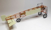
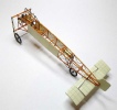
I made the fuselage frame from 1.0mm x 1.0mm styrene strips, each was cut to length then glued, using plastic glue, to the main longerons. Once all the frame was assemble and the glue allowed to dry overnight I added the front undercarriage/engine support frame work. Again plastic glue was used but backed up with some super glue. I also added a support bar under the rear of the engine which rests on either side of the fuselage frame.
Next step is to paint the entire fuselage frame to represent a wood colour, for this I will use artist oils.


As can be seen in the photos the frame had been coloured to look like wood, I used artist oils with Liquin added, it will take at least two days to dry before I can spray it with some clear orange then satin clear.


I made the two fuel tanks from 10.0mm brass rod. The short tank with the longer filler neck is 9.0mm in diameter while the auxiliary tank which is the long pointy tank is 8.0mm in diameter. The filler necks are made from 2.5mm brass rod turned down to 2.4mm and a cap filed into the end. I used a PE instrument bezel around the filler neck where it mounts into the tank. I still need to make and fit the taps which will fit on the bottom of each tank. The main tank will mount forward of the cockpit and will be supported by two brass straps, the auxiliary tank will be mounted half way between the cockpit and the tail and will also be supported by two brass straps. The auxiliary tank was used on the channel crossing Bleriot XI.


I brushed on a coat of Humbrol clear orange to the fuselage frame and also to the front undercarriage and engine support frame. This has given the “timber” a darker richer look.


I made the taps for the bottom of the two fuel tanks. I used a short length of 0.8mm brass tube and fitted a small brass nut over one end, I drilled a 0.4mm hole into the side of the tube and fitted a handle made from a piece of 0.3mm brass tube bent to the appropriate shape and flattened on one end, the completed taps are glued into holes drilled into the bottom of the tanks.


The main and auxiliary fuel tanks are now fixed in position. I have completed the fuselage frame rigging on the two sides, still need to do the top and bottom of the frames. I am using 0.12mm monofilament for the rigging, there are turnbuckles on every run, these are made from 0.5mm brass tube cut to 2.0mm in length, I insert an eyelet into each end, these are made from twisted 0.13mm copper wire with a 0.3mm eye, CA holds them well into the brass tube. I will need to make quite a few of these turnbuckles for this aeroplane. The cockpit floor is made from styrene sheet cut to size and scored to represent boards.


I added the side “fabric” to the opposite side of the fuselage. I also made and fitted an instrument and a switch to the inside of the cockpit framework. I added an electrical cable to the switch and it runs forward to the magneto, a length of copper wire is fitted in the back of the instrument and runs to the engine. The upper rigging masts have been made from 0.7mm brass tube, I cut each mast leg off the plans then cut another length for the main support between the two masts. The top ends were flattened and a 0.3mm hole drilled, the same was done to the ends of the main support. I inserted short lengths of 0.3mm wire into the bottom of the four legs, these fit into 0.3mm holes drilled into the fuselage frame at the appropriate positions. I also had to make a double pulley to mount at the rear upper end of the mast assemble, this will take the cables for the wing warping. The front of the mast has two angled brackets to take the wing rigging cables. I rigged the mast assembly with 0.12mm monofilament and used my own home made turnbuckles. The whole rigging mast assembly is very strong and rigid so it will have no problems holding the weight of the wings. I also fitted the forward wing mounting tube, this is a fairly large tube but is scaled from the plans.


The tail plane is made up of two sheets of 0.25mm styrene sandwiched together and
taped around a bottle to get the shape required, once the glue dries the shape is
retained. The rudder is made from a piece of 0.5,, styrene sheet cut to shape. The
ribs and spars are simulated using Bob’s Buckles “strippers” which have been supplied
in three sizes, I used the 0.5mm and the 0.75mm strips. These strips are a low tack
self adhering vinyl which hold well and paint well, I used Gunze acrylic which had
no effect on the strips. To assist in holding the strip where they meet at the trailing
edge I applied just a small drop of CA, this stops them from wanting to lift. When
the strips are first removed from the backing paper they are fully charged with static
electricity and are attracted to anything near-


I have painted the two side fabric panels to match the tail, I used Gunze Off White
sprayed straight from the bottle. I pre-


I made the rear wheel, the rim was cut from a length of PVC pipe then I drilled 24 holes to take the spokes. The hub is a piece of 1.5mm brass tube with two styrene washers, these will support the spokes.


The spokes are made from 0.1mm invisible thread and are held in position with CA. The wheel was painted a dark grey then a rubber O Ring fitted for the tyre. All of the rear wheel undercarriage frame is made from 0.5mm copper wire bent to the appropriate shapes, a length of 0.4mm brass tube was used for the axle so 0.4mm holes had to be drilled in the flattened ends of the copper wire. As this model is based on the channel crossing Bleriot XI which had the auxiliary fuel tank at the rear of the fuselage, the rear wheel was locked and was not steerable. I still need to add two more struts to the rear wheel undercarriage.


The main wheels for the Bleriot XI where 28 inch bicycle style wheels and very narrow. I made these wheels by firstly cutting the rim from a plastic disc I found that are used in sliding doors, the photo shows what the disc looked like before shaping then the completed wheel on the model. it has an inside diameter just right. Once cut and shaped the rims where drilled to take the spokes, I used a 0.3mm carbide drill bit. The hub is a short length of 1.5mm brass tube the two styrene washer cut and place over each end of the tube. I needed to drill holes in the small styrene washers to coincide with the holes in the rim, again I used a 0.3mm drill bit. I laced the wheels using 0.1mm invisible thread by firstly gluing the thread into the hole in the hub, once dry I threaded the spoke through the rim, pulled it tight then added CA to hold it in place. The jig I used is very simple as can be seen from the photo, it is important to make sure the rim and hub are centre to each other.


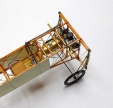
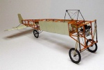

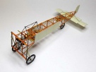
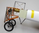
The main support arms are made from 0.7mm brass tube, these where flattened at each end and a 0.4mm hole drilled into each flattened area. The front wheel stay is a piece of 0.65mm copper wire bent to the appropriate shape and cut to length, the two ends were flattened and drilled. I drilled a 0.4mm hole through the sliding sleeve on each of the undercarriage legs, this is where the top of the support arms are fitted, I used a short length of 0.4mm brass tube to secure the assemble to the legs followed by super glue. An axle was put into the wheel hub the the two support arms and the forward stay where fitted and glued. I used an O Ring for the tyres, I had to find a thin O Ring to suit the narrow rim. The main axle is a length of 0.9mm brass tube. I still need to add the spacers between the two main support arms.
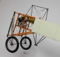
The bottom rigging mast has been made and fitted, it is constructed of four pieces of 0.8mm brass tube. Both ends of the tube was flattened and 0.4mm holes drilled, the flattened ends where bent to the appropriate angle to sit on the fuselage frame and is held in place with 0.4mm brass tube and CA. Where the four tubes meet I inserted the wing warping actuating arm then glued all four pieces together, onto ech end of the main pin I made and fitted the wing warping cable pulleys. The paper wrapped around the fuselage is there to protect the paint while I handle the model. I also fitted the two anti shimmy shock springs to the undercarriage.
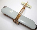

The wings have been made up with 5 layers of 0.75mm styrene sheets. I glued two sheets, which had been cut to shape, then clamped them in my jig overnight. Next day I glued another two sheets to the first two and again left them overnight in my jig. The last sheet was glued and again clamped, it needed about four hours to dry. Once the glue had dried the curve of the wing remained and was very rigid making sanding quite easy. It took a lot of sanding to get the wings to their correct shape and aerofoil section.


The wings have been sprayed with automotive primer and sanded smooth. The ribs are simulated with Bob’s Strippers, they are 0.5mm wide vinyl and are self adhering, they come on a card backing and are very easy to remove and use. They stick well once pressed firmly onto the wing. Once all the strips were applied I sprayed the entire wing with the primer again, once dry I smoothed it off with 0000 steel wool which gives a very smooth and glossy finish. I fitted a 0.4mm steel pin to locate the rear of the wing to the fuselage, this pin goes through the fuselage frame and is held in place with CA and a nut on the inside of the fuselage. As can be seen in the photos the wings are self supporting, they droop slightly but this will be rectified once the wings are glued in place. Wing painting is next once the paint turns up.


The first picture show the primer pump made and fitted to the top of the fuselage frame, 0.4mm copper wire runs from the pump to the top of the fuel tank. You will also notice I added the fuel tank overflow pipe. The second picture shows the fuel tank overflow pipe added to the front of the fuel tank.
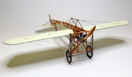
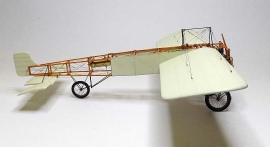
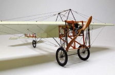
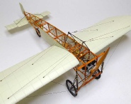
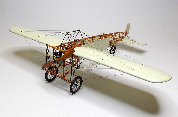
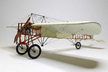
COMPLETED MODEL
The wings attached very easy and are held in place with five minute epoxy, the glue was placed inside the holes where the pins went and also spread along the wing root where it touches the fuselage. The rigging was done using 0.12mm monofilament and painted Mr Metal Color Stainless once each line was fitted.All of the turnbuckles are home made, there is not a lot of rigging on the wings of this aeroplane so it was quite an easy job. I enjoyed this build and didn’t come across any real dramas, the onlt issue was finding the correct information for the particular version I wanted to build..
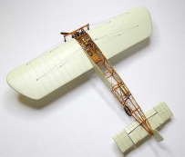
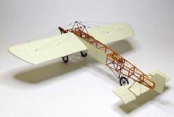

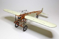
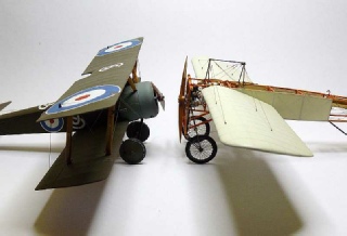
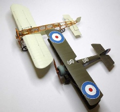
A SIZE COMPARISON WITH A SOPWITH PUP
 Index
Index