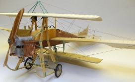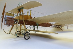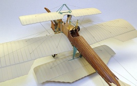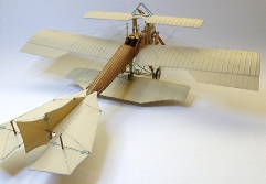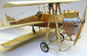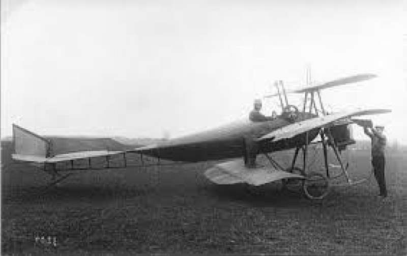
The Battaille was a triplane with the top and bottom wing having variable incidence while the centre wing was fixed just like a conventional aeroplane. The entire frame was constructed of timber including the boat style fuselage. The engine was a Gregoire (gyp) four cylinder 40hp water cooled engine, it was mounted inverted to lower the centre of gravity. Besides it odd looks apparently it flew quite well but like all aircraft of that time it suffered from being underpowered. I will attempt to scratch build this plane in 1:32 scale but I do not have any plans to follow, so construction will be taken from photos and rough drawings plus some scale plans I drew.

As can be seen by this photo the undercarriage, fuselage and top wing support is made up of quite large sections of timber. I want to replicate this as near as possible so I am using a very close grained timber not only for the appearance but for the strength as well.


The timber I am using is 0.3mm thick so I cut 0.3mm strips, I used my razor saw for cutting the fine grain timber which did a beautiful job. I then cut a nick in the timber and bent it to the appropriate angle, all four pieces are the same angle, I used wood glue (PVA) to glue the timber. Once dry I began sanding the pieces, the top and bottom of the legs are left square as well as a section near where the bend is, the remainder of the timber is sanded to an oval shape.


The fuselage support and undercarriage legs cross members were a little difficult to make. They need to be about the same size timber as the legs so I cut the shape from a solid piece of the same timber as I used for the legs, a very tight grained timber. I then glued the legs to either side of the timber using five minute epoxy. The length of the legs will be adjusted once both sections are made.


I cut the bulk of the timber away using my Dremel, care must be taken not to stress the legs. To finish off the sizing I used a drum sander in my Dremel, this allowed me to sand reasonably close. I used a sanding stick to round off the edges and to smooth off the finish. Because of the direction of the grain on the piece of timber I had to glue the legs on first to give strength to the timber once it was cut out, otherwise the thin downward facing pieces would easily have broken off.

The two sets of legs have now been completed, the front set has the support rod running across the two legs, this rod is made from a length of 0.6mm spring steel wire. I also need to add some metal brackets to the legs, I’m still contemplating the way to approach this.


I made the undercarriage skids from styrene. I firstly glued two lengths of 1.5mm x 1.0mm strips giving me a length 3.0mm x 1.0mm. To the bottom of these I glued a length of 3.0mm x 0.3mm strip and while the glue was still wet I clamped the skids to a piece of 38.0mm aluminium tube, the clamps were positioned in such a way as to give me the correct upturned front section of the skids. I allowed the skids to dry overnight, when the clamps were removed the skids retained their shape, they were then cut to length.

I will be using a pair of Steven Robson superb spoked wheels for this build, the wheels come with two sizes of rubber tyres, I am using the thinner of the two. I will hunt around to see if I can find a pair of whitish O Rings.

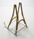

I have assembled the timber undercarriage/fuselage support assembly onto the skids. I used five minute epoxy to hold it all together as I needed it to be strong. I now need to make the metal covers to go over the top of the legs, this is where the mechanism will be fitted to actuate the variable incident on the top wing.


The wheels temporarily fitted just to give an indication of what the undercarriage assembly will look like. I need to wrap bungee cord around the axle and the skids to act as suspension. The wheels are a little larger than what is required but they are close enough for me.


I have added the top to the legs, these are made from 0.3mm styrene sheet and glued to the timber with five minute epoxy. These will be represented as metal once painted with the majority of them inside the top wing, the larger rod will support the wing. I still need to make and fit the gear mechanism for actuating the wing variable incidence.


The bell crank assembly at the rear of the frame work is, I presume, for actuating the centre wing ailerons, I need to do some more research into this but I made this assemble from photos of the restored example in the museum. The frame protruding rearwards from the timber work mounts under the fuselage just below the cockpit.


Some more photos showing the bell crank mechanism, the close up photos give a good
indication of what the set-


I coated the wood with a mixture of Humbrol Gloss Cote and a few drops of Humbrol clear orange, this gives a natural hue close to what the restored example looks like, I wanted a pine look which I think I have achieved. The green is a mixture of Humbrol No.65 with Humbrol No.226, I just kept adding drops of the 336 until I was happy with the colour.


The brackets at the base of each leg are made from 0.03mm styrene sheet cut to shape and 0.4mm holes drilled. They were firstly glued to the styrene skids then when dry held against the legs with a drop of CA. The retaining straps around the front legs and around the nose of the skids are made from thin strips of Tamiya tape applied and then painted with the green paint.
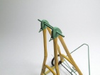
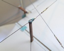
I made the two rigging brackets that mounted to the top of the mast assembly. I made these from thin strips of brass sheet bent to the appropriate shape, I then drilled 0.4mm holes to take the mounting bolt and also a 0.4mm hole for the rigging cable, this is quite a strong mounting.
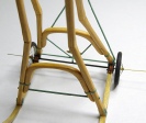
The undercarriage suspension consists of eight brackets, two each side of each skid, a 0.4mm hole was drilled through each bracket. I used plastic tubing to simulate the elastic cord, this was in two lengths on each side and sat over the axle then was held down at each end by a bolt passing through the brackets. I painted the brackets and axle with Mr Metal Color Dark Iron and the elastic suspension with Humbrol No.62 Leather


These two photos show the undercarriage frame nearly completed, the wheels are temporarily fitted at this stage. More brackets will be fitted to the frame but these will be in conjunction with the fuselage frame.


Work on the fuselage frame has begun. The spine of the frame is made from 1.0mm x 2.0mm styrene strips while the two longerons are made from 1.0mm x 1.5mm styrene strips, the cross members are also made of 1.0mm x 1.5mm strips. The curve at the front of the spine was created by clamping the strip to a tube then pouring boiling water over it followed by cold water.


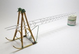
This series of photos show the fuselage frame all together, I still need to add all the metal brackets. The braces are made from 1.0mm x 1.0mm styrene strips. As can be seen in photo No.3 it is a long way from the back of the frame to the front of the engine mounts, it is a very long fuselage and there is still the tail to be fitted which will add more length to the assembly. Looking at photos of the original and the restored examples there is an enormous amount of rigging on the fuselage frames, this will take some figuring out as will the metal brackets which are quite numerous. The hole in the frame just behind the undercarriage legs is where the pilot will sit, poor guy…….. The photo with the wheels fitted gives an indication of what the plane will sit like, the tail skid will raise the tail slightly.
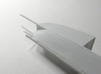

I have started the planking on the side of the fuselage, for this I am using 2.5mm x 0.5mm styrene strips, for rapid setting I am using super glue to fit the planks. The box section is the top of the fuselage, this was made of plywood on the original. The planking is a very time consuming and slow process.

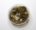
The top wing incidence actuating gear has been fitted to the top of the undercarriage legs. This gear is a watch/clock part which I purchased from a Steam Punk supplier in England. The photo shows the container of watch/clock parts I received, there are hundreds of different sized gears and cogs all which will be very useful over time. This container of pieces only cost $15.00 and was found on ebay.



I have started the planking on the top half of the fuselage, for this I am using the same as the bottom, 2.5mm x 0.5mm styrene strips. I had to make and fit the top bulkheads for the planks to glue to, most of this is guess work as I have no plans or dimensions. The planks on this aeroplane had cover strips where each plank joined, for this I am using 0.3mm monofilament, once painted it should look the part.


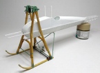
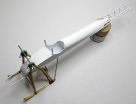
I completed the planking on the top half of the fuselage, it went a lot easier than what I thought it would. The shape looks very similar to photos of the real aeroplane so I must have done something right. I still need to add the cover strips to the planks on the top of the fuselage. I also cut out the hole for the cockpit, this was cut into shape with my Dremel with a drum sander then finished off with fine sand paper, cockpit padding will be fitted also.

I made a seat for this model, it is cut from styrene sheet with holes drilled in the back. I still need to add a seat cushion and edge beading around the seat back. The green background shows the fuselage a bit clearer, it will all come together once paint is added to make it all look like timber.


All the cover strips are now added and the entire model has been given a coat of paint ready for the wood grain, I will be using oil paints to simulate the wood. The photo with the model inverted shows the bow like front to the bottom half of the fuselage, boat building skills would have been needed to build this aeroplane. The last photo is for size comparison, once the wheels are added the height of the plane will be much the same as I have seen in original photos


I have made the fin and rudder from 1.0mm styrene sheet, it has been cut to shape then sanded to give an airfoil section. The hinges are made from brass sheet bent to fit around the 1.0mm thickness styrene sheet, 0.4mm holes were drilled for the hinge retaining screws. I also made the rudder control horn and fitted it to the rudder, The tail skid is made and fitted, it is fastened to the rudder post with another piece of brass cut and bent to shape


I applied oil paint over a base coat of Gunze off-


The contrasting colours between the undercarriage frame and the fuselage colour is just like the restored example in Brussels, I can imagine that the large undercarriage frame would have been constructed from a very light timber to keep the weight down as much as possible, even so with all the other timber that goes into this aeroplane it would have been quite heavy, and underpowered.
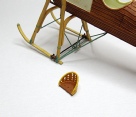

The seat back has been given a coat of yellow ochre oil paint while the seat cushion has been painted with Humbrol leather No.62. I will also paint the leather colour around the edging on the back of the seat as it would have been a type of padding.


The tail plane has been made from sheet styrene cut and sanded to shape. The twelve hinges are made from 2.4mm wide brass strips cut, drilled and bent to shape. The shading is being done with lead pencil and the surfaces will be sprayed with Hobby Colour H313 Yellow FS33531 which is on order at present and should be here in a day or two.


I have made and fitted all the metal brackets which hold the fuselage rigging wires. The brackets are made from strips of brass sheet drilled and cut to size then sanded to shape. Each bracket has a 0.3mm brass pin that is glued through the bracket and into the fuselage frame. All the brackets have been painted with the same colour I used for the metal fittings on the undercarriage frame work.


These three photos show a mock-
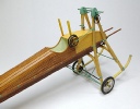


The plywood has been added to the top front of the fuselage. I printed the plywood decals myself simply by finding an appropriate plywood picture on the net then downloading it into my drawing program where it was resized to 1:32 scale. The resulting images were printed on my new Brother inkjet printer which produces very high quality prints. Once dry I sprayed the decals with a coat of clear lacquer, they were then applied as normal decals. The top and bottom wing incidence adjusting wheels have been made and added to the right side of the fuselage, these where made from watch gears with small rubber tube wrapped around the outside. The undercarriage cradle has also been fitted to the fuselage and brackets added where it joins the fuselage, more brackets were added on the rear leg above the fuselage, these will take rigging wires and a stay back to the adjusting wheels. I made the fuel filler from 1.5mm brass tube and a plastic top shaped and fitted, it’s position is purely speculation.


The tail has now been painted with the Gunze yellow as mentioned earlier, the shading is prominent but not too much so. The side photo show the shape of the fin and rudder, I have also added some metal brackets to take the rigging lines.


Before the tail can become a permanent fixture I need to complete the fuselage rigging, this has now been done. There is a total of 26 turnbuckles on this section of the rigging, the rigging line is 0.12mm monofilament and it is all held together with CA., the tail can now be fitted.
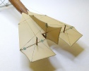


The tail plane has now been fixed to the fuselage frame, I did this using plastic cement followed up with CA to give some added strength.The rigging on the top of the tail plane has been completed, for this I used 0.12mm monofilament, once fitted it was painted with Mr Metal Color Stainless. The tension lines running back from the control horns onto the rudder and elevator are rigged with 0.1mm smoke colours invisible thread. The side on photo show the tail skid and the tail skid suspension spring which is mounted on the top of the bottom fuselage stringer. The overall photo shows the tail now in its nearly completed state.

The first photo shows the metal bracket I made to slip over the top of the elevator control horn, this was made from 1.0mm wide brass sheet bent to the appropriate shape then a 0.3mm hole drilled for the control cable, the bracket was CA’d onto the control horn. The next photo shows another bracket that is fitted to the top of the fin, this is also made from brass sheet with 0.3mm holes drilled. The bracket is held to the fin post with a 0.3mm brass pin and CA.


The first photo shows the undercarriage suspension set-
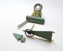


These photos show the components I need to make to make the lower wing mount and incident adjusting mechanism. The small gears are from watch/clock parts with brass sheet used to make the mount. The main mounting bracket which fits onto the fuselage is fashioned from 1.0mm styrene sheet, the small mounting lugs are from 0.5mm copper wire flattened and drilled with a 0.3mm drill bit. The mount is fixed to the fuselage with 0.3mm brass pins and super glue. The assembly may appear to be a little fragile but now that all the glue has set it is quite a strong unit. The bottom wing will sit very low in relation to the fuselage but a check with photos shows that what I have here is correct.


I started the engine by using the body of a 5ml syringe as the crank case, it fits perfectly between the engine bearers. I added the engine mounts using styrene sheet cut to shape and fixed to the crank case with CA. The cylinders are cut from 4.0mm aluminium rod and fitted into holes drilled into the crank case. This engine was mounded inverted to lower the centre of gravity and to also give the pilot a better field of view while looking forward. The box? sitting on the crank case to me appears to be the oil tank, all I have to go by are three very fuzzy photos, from here on end I will call it the fuel tank. I made the tank from styrene sheet and used RB Motion brass nuts for the detail. The rivets around the top of the tank are lengths of 0.3mm brass tube.


The accessories added to the engine are from my spares box, I tried to match the appearance as much as possible with the very unclear photos I have of this engine. I still need to add fuel/oil lines but these will be added once the entire engine is near completion. I painted the fuel tank and accessories with Mr Metal Color Brass, the mounting plate which is bolted to the crank case will also be painted brass, the crank case will be painted aluminium. The unusual aspect of this engine is that the cylinders are fully encased with a water jacket, another odd or novel aspect is the fact that some of the push rods pass through sleeves inside the exhaust pipes. Not having any good reference material makes it very difficult to construct this engine, most of it will be guess work but with my engineering knowledge I will attempt to assemble it to represent a real engine.
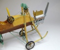


I have encased the cylinders with styrene sheet and used 0.3mm brass tube to simulate rivets. The plumbing is made from 1.0mm copper wire bent to shape, this side of the engine will also have the four spark plugs, the holes are already drilled. The crank case has been given a coat of Humbrol 27001 Aluminium. Once I finish off the bottom end of this engine it will be painted the same colour. I now need to make and add the rocker arms, valve springs and push rods.


The engine is nearly completed. I made and added the push rods, rocker arms, valve springs and added some water plumbing to the cooling jacket, these of course will be connected to the radiator. I also fitted four spark plugs and a magneto plus two drive gears. The last photo shows the engine ready to be installed into the airframe.
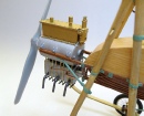


This series of photos shows the engine just sitting in the airframe, I still need to add some fuel/oil lines, ignition leads to the spark plugs and maybe a few other lines as well. Once the radiator is made and fitted it will cover a majority of the engine from the engine bearers down. Building this engine was very difficult as all I had for reference were three blurry photos of one of these engine at the Paris Aeronautical show back in 1910, I also had some photos of the engine fitted to the aircraft but they showed very little in the way of engine detail.

I made the two radiators from 2.0mm half round styrene strips and 0.4mm copper wire. I laid the copper wire on my bench with a shorter length of 0.4mm wire to act as a spacer, once they were all laid square and pushed up close together I placed a length of 6.0mm wide Tamiya tape across the whole lot to hold them together. I then had the flat side of one of the half round strips facing up and I placed the copper wires onto the plastic strip, I used CA to hold it in place. I repeated the process with the second plastic strip and then I glued the second half of the strip onto the top of the strips already laid, this now forms a 2.4mm rod with just a small amount of filler needed to fill the small gap between the two halves. I painted the radiators with Humbrol Antique Bronze then polished it with 0000 steel wool, I left the copper wire natural. The series of photos below show the two radiators fitted to the aircraft.


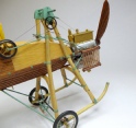
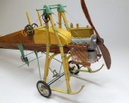

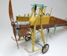


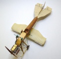

The first of the wings is now made. I constructed the wing with two layers of 1.0mm styrene sheet, I glued the two sheets together and while the glue was still wet I taped the wing around an aerosol can to get the shape required, I left it overnight before removing the tape. The dried wing is very rigid and retains its shape well, I then sanded the leading and trailing edges to the desired shape. I used 1.5mm half round styrene strips for the wing ribs, these were glued to the top surface of the wing. The feather at the rear of the wing was cut from 0.5mm styrene sheet and glued to the main wing, the ribs on this section are 1.0mm wide Bob’s Strippers. The bottom of the entire wing has ribs simulated using Bob’s Strippers 1.0mm wide. The entire wing was painted with automotive filler/primer then sanded between the ribs to give the scalloped look, this process had to be repeated about three times before the desired appearance was achieved. The wing was then painted with the top coat and when dry was fixed to the airframe.

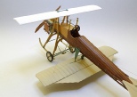


The bottom wing has now been fitted and some rigging added to improve stability of the wing. The top wing has been made using two layers of 1.0mm styrene sheet glued together then taped around an aerosol can to the correct shape. I still need to add the ribs which will be 1.0mm half round styrene strips. I had to cut slots into the wing to accommodate the top of the undercarriage frame and the mechanism for the wing actuating. There will be a frame work made and fitted to the top of the wing, this is for the wing rigging so will be made reasonably strong, probably from brass tube. As ugly as this aeroplane is it is starting to look like the Battaille. I have noticed that the restored example in the museum is a bit different to the original aircraft shown in photos I have, apart from having the incorrect engine there are some very obvious differences with the museum display aircraft.


The centre wing has now been built, it was done in the same manner as the other two wing. I have glued the 1.0mm half round strips onto the top of the wing to simulate the ribs. There will now be a lot of spraying and sanding to achieve the scalloped look between the ribs. The centre wing has dihedral which is achieved by bending the wing locating pins up to the appropriate angle. In these photos the centre wing is sitting in position supported only by the locating pins, no glue is used at this stage. The model has become quite heavy with all three wings fitted which is putting some strain on the tail skid, I may have to strengthen it with a steel pin. The next update will be photos of the completed model which hopefully won’t be too far away.
I thoroughly enjoyed building this model, but the job was made difficult by the lack of plans or drawings and not having any dimensions made life very difficult. It is a shame that the Museum in Brussels would not answer my emails and give me some information on this particular aeroplane, just a few simple measurements was all I was asking for. All the rigging was done using 0.12mm monofilament with home made turnbuckles. Many thanks to Steven Robson for supplying me with the spoked wheels and to The Micro Group for their magnificent laminated wood propeller.

